700 SERIES LAWN TRACTORS
17
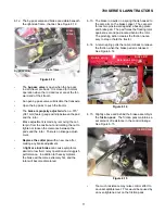
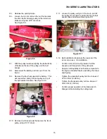
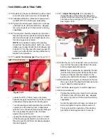
9.6.
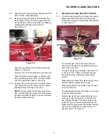
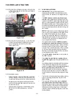
If it is necessary
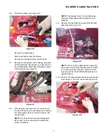
to remove the brake rod from
the tractor
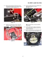
, the easiest method is as follows:
See Figure 9.6.
•
Remove the cutting deck.
•
Disconnect the front of the brake rod from the
brake pedal assembly by removing and discard-
ing the cotter pin, removing the washer, and pull-
ing the rod out of the hole in the bellcrank on the
brake cross shaft assembly.
•
Pivot the spring that connects the brake rod to
the caliper up and outward to unhook it.
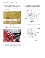
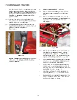
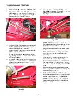
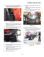
9.7.
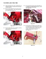
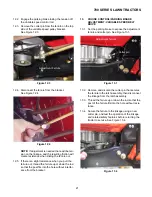
Brake rod and spring installation can be accom-
plished by reversing the removal process.
See Figure 9.7.
NOTE:
Confirm correct operation of the brake /
clutch pedal mechanism and all tractor safety
features before returning the tractor to service.
Figure 9.6
Brake rod
Cotter pin
Washer
Figure 9.7
Spring
(connecting brake rod
to cam arm on caliper)
10.
PARKING BRAKE : HYDROSTATIC DRIVE
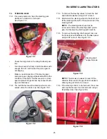
10.1. The parking brake is operated by small lever on
the left side of the dash panel. The label
describes one end of the lever’s travel as “ON”,
and the other end as “RUN”.
10.2. Moving the lever up to the “RUN” position allows
the brake pedal to come up, releasing the brake
and engaging the drive belt.
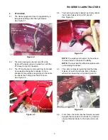
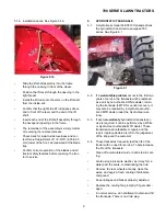
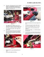
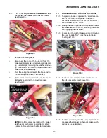
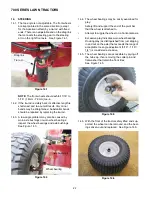
10.3. Depressing the clutch / brake pedal and moving
the lever back to “ON” locks the pedal down.
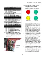
See Figure 10.3.
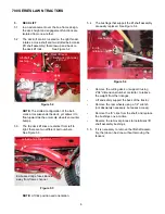
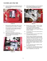
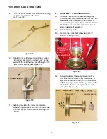
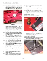
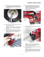
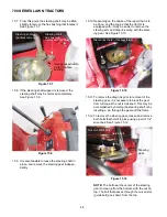
10.4. The lever moves an adjustable rod that moves
the latch assembly. See Figure 10.4.
10.5. The latch assembly should be adjusted so that it
depresses the plunger on the park brake switch,
and locks the pedal down.
Figure 10.3
to ON
Pedal down
Figure 10.4
Adjustable rod
Latch assembly
Содержание 700 Series
Страница 2: ......
Страница 4: ......
Страница 50: ...700 SERIES LAWN TRACTORS 46 ...
Страница 52: ...700 SERIES LAWN TRACTORS 48 ...

