700 SERIES LAWN TRACTORS
6
5.
DECK LIFT
5.1.
In an advancement over the box-frame design,
the deck height and engagement functions are
isolated from one-another.
5.2.
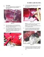
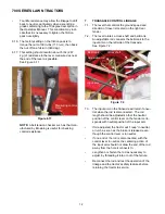
The deck lift control, located on the right fender,
rotates a cross-shaft and two slotted bell-cranks
(lift shaft assembly) that draw up and back on
the deck lift rods. See Figure 5.2.
NOTE:
The slotted configuration of the bell-
crank arms suspends the deck, yet allows it to
float upward as the anti-scalp wheels encounter
bumps.
5.3.
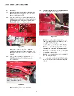
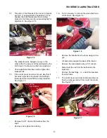
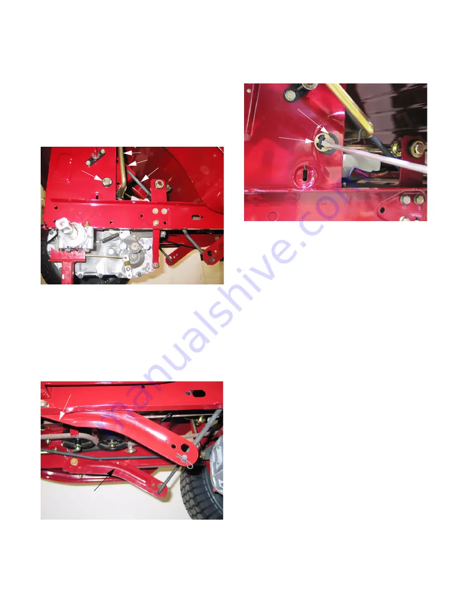
The the deck lift links are distinct from left to
right: there are two different part numbers.
See Figure 5.3.
NOTE:
Lift link position and orientation.
5.4.
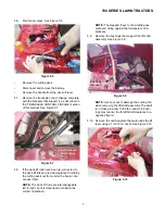
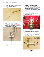
The bushings that support the lift shaft assembly
are easily replaced. See Figure 5.4.
•
Remove the cutting deck, or support it using
2”X4” dimensional lumber or similar, to relieve
the weight from the linkages.
•
Lift and safely support the back of the tractor.
•
Remove the rear wheels using a 1/2” wrench
(not absolutely necessary, but eases access).
•
Remove the “E” clips from the shaft, and replace
the bushings one at a time.
•
Reverse the removal process to install deck lift
shaft assembly bushings.
5.5.
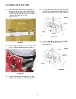
If it is necessary to remove the lift shaft assem-
bly, the job can be done without removing the
fenders.
Figure 5.2
Deck lift lever
Bellcrank (right side)
Lift rod
Lift-shaft
bushing
Figure 5.3
Left-side has flat at front
Embossed ridge faces inboard,
away from frame channel
Figure 5.4
E-clip
retaining ring
Hex bushing
Содержание 700 Series
Страница 2: ......
Страница 4: ......
Страница 50: ...700 SERIES LAWN TRACTORS 46 ...
Страница 52: ...700 SERIES LAWN TRACTORS 48 ...


