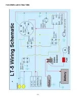
700 SERIES LAWN TRACTORS
31
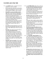
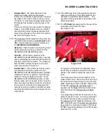
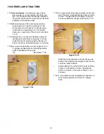
17.2. The
Key Switch
is similar to those used in a
variety of MTD applications since 1999. The dif-
ference in this case is that it is incorporated in
the same housing as the RMC module; the two
items are not available separately.
See Figure 17.2.
17.1-17.9
Key Switch and Module
17.3
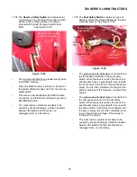
Key Switch OFF
17.4
Key Switch START
17.5
Key Switch RUN
17.6
Key Switch REVERES CAUTION
17.9
Module Function
17.1O-17.24 Single-point Diagnosis
17.11-17.23 RMC Plug Test
17.14-17.17 Pigtail Plug Test
17.16
Pigtail Plug Test: seat safety
17.17
Pigtail Plug Test: PTO safety
17.19
RMC Plug Test: reverse safety
17.2O
RMC Plug Test: ground
17.21
RMC Plug Test: power
17.22
RMC Plug Test: park-brake
17.23
RMC Plug Test: module arm signal
17.25-17.31 Direct testing of switches
17.25
Direct test: PTO safety switch
17.26
Direct test: Brake safety switch
17.27
Direct test: park brake safety switch
17.28
Direct test: reverse safety switch
17.29
Direct test: seat safety switch
17.3O
Direct test: starter solenoid
17.31
Lighting circuit
17.32
Fuse and Ammeter
17.33
Engine harness connector: White
17.34
Engine harness connector: Troy-Bilt
17.35
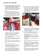
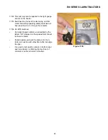
Voltage drop test
Electrical Diagnostic Over-view
Figure 17.2
RMC Module
Key switch
Ammeter
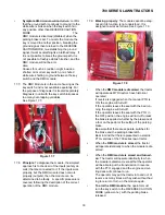
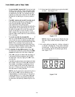
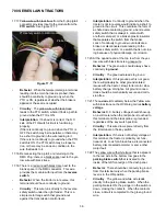
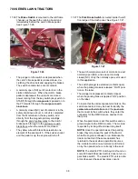
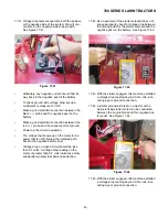
17.3. In the
OFF
position, continuity can be found
between the M, G, and A1 terminals.
See Figure 17.3.
•
M is connected to the magneto by a yellow wire,
G is connected to ground by a green wire, and
A1 is connected to the after fire solenoid and
alternator.
•
In the
OFF
position, the magneto primary wind-
ings are grounded, disabling the ignition system.
The alternator output that normally keeps the
after fire solenoid powered-up is given a more
direct path to ground, depriving the after fire
solenoid of power. This turns-off the fuel supply.
•
Symptom
-engine runs with key in OFF position:
The key switch is not completing the path to
ground either because of an internal fault or a
bad ground connection elsewhere in the har-
ness. Check continuity between M, G, and A1
terminals with key switch in OFF position.
Check green wire continuity to ground.
•
Symptom
-loud “BANG” when key is turned to
the OFF position: The after fire solenoid is not
closing, either because it is physically damaged
or the alternator output is not getting grounded.
Check continuity between G and A1 terminals.
Check continuity from red wire to afterlife sole-
noid.
•
Symptom
-Engine runs 3-5 seconds after key is
turned to OFF position: The after-fire solenoid is
turning-off the fuel supply, but the ignition is con-
tinuing to operate. Check continuity between the
M and G terminals in the OFF position. Check
continuity from yellow wire connection all the
way to the spade terminal on the magneto.
Figure 17.3
Содержание 700 Series
Страница 2: ......
Страница 4: ......
Страница 50: ...700 SERIES LAWN TRACTORS 46 ...
Страница 52: ...700 SERIES LAWN TRACTORS 48 ...

