700 SERIES LAWN TRACTORS
13
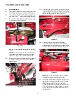
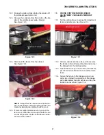
7.4.
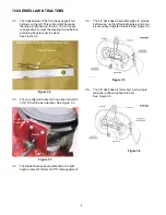
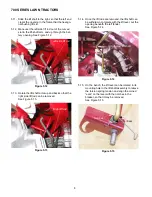
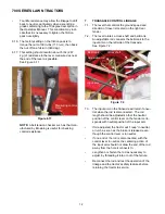
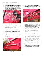
The pitch on the threads of the rod is 16 threads
per inch. If an adjustment of less than 1/16” is
needed, the bolts that secure the mounting
bracket to the frame can be loosened slightly for
adjustment. See Figure 7.4.
•
The bracket can be budged one way or the
other, within the amount of travel allowed by the
bolt holes in the frame, to effect an adjustment.
•
Once adjustment has been made, tighten the
bracket bolts.
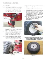
7.5.
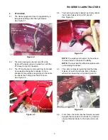
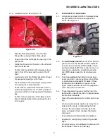
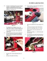
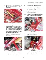
If the control lever develops enough play that it
becomes imprecise, the plastic hex bushings
that support the cross shaft are easily replaced.
See Figure 7.5.
•
Remove the “E” clip and flat washer from the
shaft.
•
Remove and replace the bushing.
Figure 7.4
Bracket
bolts
Adjustment
Figure 7.5
Hex bushing
Flat washer
E-ring
Cross shaft
Fan
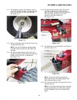
7.6.
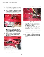
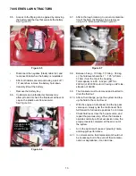
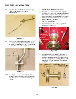
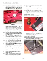
If it is necessary to remove the cross-shaft and
control lever: See Figure 7.6.
•
Remove the handle from the lever using a blow-
gun.
•
Lift and safely support the back of the tractor.
•
Remove the rear wheels using a 1/2” wrench.
•
Disconnect the rod from the bellcrank to the
input arm.
•
Remove the bushings - or - unbolt the brackets
from the frame.
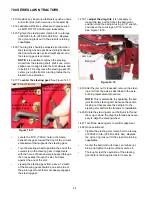
7.7.
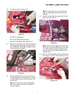
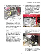
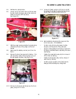
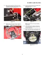
The control lever and cross shaft assembly can
then be maneuvered out from under the fender.
See Figure 7.7.
Figure 7.6
Figure 7.7
Содержание 700 Series
Страница 2: ......
Страница 4: ......
Страница 50: ...700 SERIES LAWN TRACTORS 46 ...
Страница 52: ...700 SERIES LAWN TRACTORS 48 ...

