700 SERIES LAWN TRACTORS
14
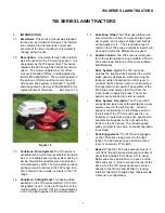
7.8.
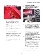
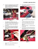
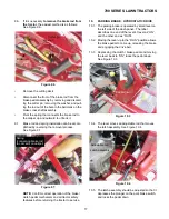
The cross shaft, control lever, and torsion spring
can be disassembled on the bench.
See Figure 7.8.
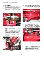
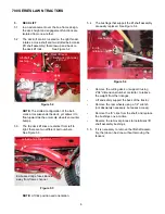
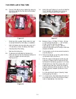
7.9.
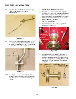
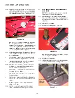
Rotate the lever to relieve tension from the tor-
sion spring, and align the coined “ears” on the
lever with the slots that they pass through in the
cross shaft assembly. See Figure 7.9.
7.10. Install by reversing the removal procedure.
Replace any worn parts and test-run the mower
to confirm proper function before returning it to
service.
8.
DRIVE BELT: HYDROSTATIC DRIVE
8.1.
To remove the transaxle drive belt, begin by
removing the cutting deck and the front deck sta-
bilizer link. The procedure in the operator’s
manual or the procedure described in the “DECK
REMOVAL” section of this manual will provide
some guidance, if necessary.
8.2.
Set the Parking Brake.
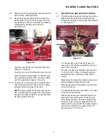
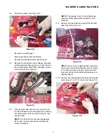
8.3.
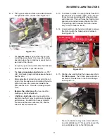
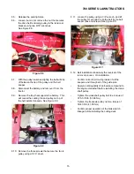
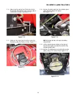
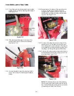
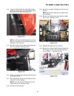
Remove the crankshaft pulley using a 5/8”
wrench. See Figure 8.3.
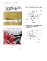
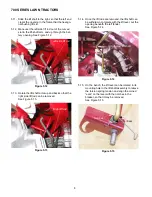
8.4.
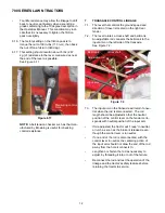
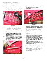
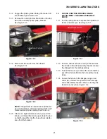
Pulley Hardware: The pulley is secured by a
bolt, lock washer, and a heavy flat washer. A
spacer is positioned above it on the crankshaft,
with the top edge radius matching the step in the
crankshaft. The key is integral with the stack
pulley. See Figure 8.4.
Figure 7.8
Figure 7.9
To relieve tension
Figure 8.3
Belt keeper
screws and
spacers
Belt keeper tabs
Figure 8.4
Bolt Lock washer Stack pulley Spacer
Flat washer towards engine)
(Rounded shoulder
Содержание 700 Series
Страница 2: ......
Страница 4: ......
Страница 50: ...700 SERIES LAWN TRACTORS 46 ...
Страница 52: ...700 SERIES LAWN TRACTORS 48 ...


