5-10
Electrical Shock Hazard
Power is present during the following
tests.
WARNING
Connector
Test Points
Output
Voltage
Pins 1 & 2
Pins 3 & 4
CN153*
Pins 1 & 2
12 volts DC
* Test in “Demo Mode.”
12 volts DC
CN152
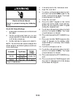
Check DC Output Voltage
1.
Unplug the microwave oven or disconnect
the power.
2.
Tilt the control panel back so you can
access the 40 W inverter board (see page
4-18 for the procedure).
3.
Set the voltmeter to measure 12 volts DC.
NOTE: The 40 W inverter output voltages that
will be tested in the following steps are shown
in the chart below.
4.
Connect power to the microwave oven.
5.
Open the oven door.
6.
Touch the voltmeter test probes to pins
1
and
2
of connector
CN152
(refer to the
photo on the previous page). The meter
should indicate 12 volts DC.
7.
Close the oven door.
8.
Press the LIGHT keypad on the control
panel and set the lights to full intensity.
NOTE: Do not press the LIGHT keypad
during the measurement.
9.
Touch the voltmeter test probes to pins
3
and
4
of connector
CN152
. The meter
should indicate 12 volts DC.
10. Press and release the OFF/CANCEL key-
pad.
11. Press and hold the TIMER keypad until a
small “d” appears on the display, (after
approximately 5 seconds), then release
the keypad.
12. Turn the microwave oven on.
13. Touch the voltmeter test probes to pins
1
and
2
of connector
CN153
. The meter
should indicate 12 volts DC.
14. Press and release the OFF/CANCEL key-
pad.
15. Press and hold the TIMER keypad until
the small “d” disappears from the display
and release the keypad.
Содержание GH9185XL
Страница 67: ...7 3 STRIP CIRCUITS MICROWAVE COOKING BLOWER FAN ON AUTOMATIC BLOWER FAN ON VARIABLE ...
Страница 68: ...7 4 COOKTOP LAMP ON VARIABLE LIGHT MICROWAVE TIME OF DAY DISPLAYED DOOR OPEN CAVITY LAMP ON ...
Страница 69: ...7 5 NOTES ...
Страница 70: ...7 6 NOTES ...
Страница 72: ...CORPORATION ...


