4-5
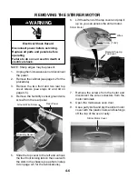
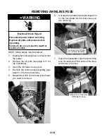
e) Remove the two screws and ground
wire from the sensor and remove the
sensor from the bracket.
f) Slide the top cover to the left and un-
hook the four front locking tabs in the
cover with the slots in the chassis, (see
the lower left photo).
g) Lift the top cover and pull the sensor
cable through the access hole, and
remove the sensor.
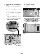
b) Disconnect the 3-wire (red, white, &
black) sensor connector from display
board connector P5.
Humidity Sensor Connector (P5)
Access Hole
Humidity Sensor
Ground Wire Screw
Screw
REASSEMBLY NOTE: When you reinstall the
humidity sensor on the bracket, be sure to
position the cable facing down, as shown in the
photo.
Electrical Shock Hazard
Connect green ground wire to ground
screw.
Failure to do so can result in death or
electrical shock.
WARNING
Top Cover
Rear Panel
Screw
Ground Wire Screw
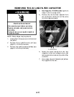
c) Remove the two top cover screws from
the rear panel.
Screw
d) Remove the two top cover screws from
the front corners.
Screw
Screw
4 Front Top Cover Locking Tabs
Position Humidity Sensor Cable Here
Содержание GH9185XL
Страница 67: ...7 3 STRIP CIRCUITS MICROWAVE COOKING BLOWER FAN ON AUTOMATIC BLOWER FAN ON VARIABLE ...
Страница 68: ...7 4 COOKTOP LAMP ON VARIABLE LIGHT MICROWAVE TIME OF DAY DISPLAYED DOOR OPEN CAVITY LAMP ON ...
Страница 69: ...7 5 NOTES ...
Страница 70: ...7 6 NOTES ...
Страница 72: ...CORPORATION ...


