4-12
REMOVING THE CONTROL PANEL ASSEMBLY,
THE POWER SUPPLY & DISPLAY BOARDS,
AND THE KEYBOARD
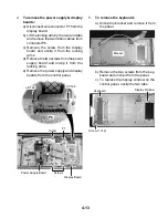
b) Disconnect wire connectors P2, P3,
P5, P12, and P14 from the display and
power supply boards.
c) Disconnect the wires from the relay
terminals.
d) Remove the green ground wire from
the control panel bracket.
e) Unhook the hinge from the slot and
remove the control panel assembly from
the unit.
f) Lay the control panel assembly on a
padded surface.
Electrical Shock Hazard
Disconnect power before servicing.
Replace all parts and panels before
operating.
Failure to do so can result in death or
electrical shock.
WARNING
1.
Unplug the microwave oven or disconnect
the power.
2.
Remove the air grille from the unit (see
page 4-11 for the procedure).
3.
To remove the control panel assembly:
a) Remove the top screw from the control
panel, then lift the panel, unhook the
side latching tabs, and tilt the top for-
ward as far as the wires will allow.
NOTE:
Sharp edges may be present.
Control Panel Screw
Electrical Shock Hazard
Connect green ground wire to ground
screw.
Failure to do so can result in death or
electrical shock.
WARNING
P14
Red & Org
Red
P12
P5
P3 P2
Relay
Ground
Содержание GH9185XL
Страница 67: ...7 3 STRIP CIRCUITS MICROWAVE COOKING BLOWER FAN ON AUTOMATIC BLOWER FAN ON VARIABLE ...
Страница 68: ...7 4 COOKTOP LAMP ON VARIABLE LIGHT MICROWAVE TIME OF DAY DISPLAYED DOOR OPEN CAVITY LAMP ON ...
Страница 69: ...7 5 NOTES ...
Страница 70: ...7 6 NOTES ...
Страница 72: ...CORPORATION ...


