background image

5-1

WARNING

Electrical Shock Hazard

Disconnect power before servicing.

Replace all parts and panels before operating.

Failure to do so can result in death or electrical shock.

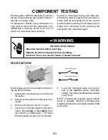
Refer to page 4-24 for the procedure for servic-
ing the door switches.

1.

Unplug the microwave oven or disconnect
the power.

2.

Disconnect the wires from the switch ter-
minals.

3.

Set the ohmmeter to the R x 1 scale.

4.

Touch the ohmmeter leads to the termi-
nals of the 

primary

 or 

secondary

 inter-

lock  switch  (normally-open).  The  meter
should indicate an open circuit (infinite).

COMPONENT TESTING

DOOR SWITCHES

Normally-Open

Normally-Closed

Discharge the 1100 W inverter before conduct-
ing any of the following tests (perform steps 1
through 4 on page 4-20).

All  operational  checks  using  microwave  en-
ergy must be done with the microwave oven
loaded with a minimum of 275 ml (9.3 oz.) of
water in a microwave safe container.

5.

Touch the ohmmeter leads to the termi-
nals  of  the 

monitor

  switch  (normally-

closed). The meter should indicate a closed
circuit (0 

).

NOTE:  Pressing  the  actuator  button  should
result  in  opposite  readings  (normally-open
should read closed, and normally-closed should
read open).

Conduct  a  microwave  energy  test  after  per-
forming any tests or repairs to the microwave.

Check  that  all  wire  leads  are  in  the  correct
position before operating the microwave oven.

Grasp  wire  connectors  when  removing  the
wire leads from microwave parts.

Содержание GH9185XL

Страница 1: ...CONSUMER SERVICES TECHNICAL EDUCATION GROUP PRESENTS MICROWAVE HOOD COMBINATION JOB AID Part No 8178229 KM 28 Models GH9185XL MH9180XL ...

Страница 2: ...and should be used for training purposes only Always use the Wiring Diagram supplied with the product when servicing the unit GOALS AND OBJECTIVES The goal of this Job Aid is to provide detailed information that will enable the service technician to properly diagnose malfunctions and repair the Microwave Hood Combination The objectives of this Job Aid are to Understand and follow proper safety pre...

Страница 3: ...ent Locations 4 1 Removing The Cabinet 4 2 Removing The Bottom Cover Hood Lamp Socket 4 3 Removing Cavity Thermostat 1 The Humidity Sensor 4 4 Removing The Stirrer Motor 4 6 Removing Cavity Thermostats 2 3 4 8 Removing The Hood Exhaust Fan Motor 4 10 Removing The Cavity Lamp Socket 4 11 Removing The Control Panel Assembly The Power Supply Display Boards And The Keyboard 4 12 Removing An Inline Fus...

Страница 4: ...t Motor Start Capacitor 5 5 Cooling Fan Motor 5 6 Hood Exhaust Fan Motor 5 6 Magnetron 5 7 Magnetron Thermostat 5 7 Inverters 5 8 DIAGNOSIS TROUBLESHOOTING 6 1 Power Output Measurement 6 1 Failure Codes 6 1 Display And Power Board Callouts 6 2 Primary Secondary Monitor Switch Checks 6 3 Touch Panel Microcomputer Board Test 6 4 WIRING DIAGRAMS STRIP CIRCUITS 7 1 Schematic Diagram 7 1 Wiring Diagram...

Страница 5: ...edmanyimportantsafetymessagesinthis JobAidandontheappliance Always read and obey all safety messages This is the safety alert symbol This symbol alerts you to hazards that can kill or hurt you and others All safety messages will follow the safety alert symbol and either the word DANGER or WARNING These words mean All safety messages will tell you what the potential hazard is tell you how to reduce...

Страница 6: ... OF Secondary Interlock Switch SZM V01 FA 32 Interlock Monitor Switch SZM VI6 FA 62 or VP 532A OF Oven Lamp Switch SZM V6 FA 31 or VP 331 A OD It is neither necessary nor advisable to attempt measurement of high voltage Attaching the adaptor ground terminal to the wall receptacle cover screw does not ground the appliance unless the cover screw is metal and not insulated and the wall receptacle is ...

Страница 7: ...trap to a green ground connection point or unpainted metal in the appliance or touchyourfingerrepeatedlytoagreenground connection point or unpainted metal in the appliance Before removing the part from its package touch the antistatic bag to a green ground connection point or unpainted metal in the appliance Avoid touching electronic parts or terminal contacts Handle the electronic control as semb...

Страница 8: ...fetyproceduresshould be exercised at all times Untrained personnel should not attempt service without a thorough review of test procedures and safety information con tained in this Job Aid WARNING TO SERVICE TECHNICIANS Whirlpool microwave ovens have a monitoring system designed to assure proper operation of the safety interlock systems The monitor switch will immediately cause the oven fuse to bl...

Страница 9: ...pping or Abuse C Before turning on the microwave power for any service test or inspection within the microwavegeneratingcomponents check the magnetron wave guide or transmis sion line and cavity for proper alignment integrity and connections D Any defective or misadjusted components in the interlock monitor door seal and microwave generation and transmission systems shall be repaired replaced or a...

Страница 10: ...mbly will normally register small emissions but they must be no greater than 4 mw cm2 to allow for measurement uncertainty NOTE Enter leakage readings in space BE FORE and AFTER on the service document All microwave ovens exceeding the emission level of 4 mw cm2 must be reported to Dept of Service for Microwave Ovens immediately and the owner should be told not to use the micro wave oven until it ...

Страница 11: ...is connected to the power line One of the IGBT switching power devices collector is directly con nected to the aluminum heat sink The aluminum heat sink may be HOT from heat energy therefore extreme care should be taken during servicing and replacing WARNING INVERTER POWER SUPPLY GROUNDING Check the high voltage inverter power sup ply circuit grounding This high voltage in verter power supply circ...

Страница 12: ...FT 10 1 0 CU FT 06 6 CU FT 12 1 2 CU FT 07 7 CU FT 14 1 4 CU FT 08 8 CU FT 15 1 5 CU FT 09 9 CU FT 18 1 8 CU FT FEATURE LEVEL 0 30 KIT IF KIT 2 22 KIT IF KIT 4 24 KIT IF KIT 5 SENSORED MODEL 7 27 KIT IF KIT FEATURE CODE C CSA APPROVED S CARRY IN WARRANTY EFFECTIVE 02 96 X IN HOME WARRANTY EFFECTIVE O2 96 YEAR OF INTRODUCTION J 2000 K 2001 L 2002 COLOR CODE B BLACK Q WHITE T BISCUIT ENGINEERING CHA...

Страница 13: ...1 9 MODEL SERIAL NUMBER LABEL AND TECH SHEET LOCATIONS The Model Serial Number label and Tech Sheet locations are shown below Model Serial Number Label Location Tech Sheet Location Behind Grille ...

Страница 14: ...ories Warm Hold 10 Power 99 Min 99 Sec Max 10 Power 99 Min 99 Sec Max Jet Start Yes 30 Sec Yes 30 Sec OTHER FEATURES Pause Door Open Door Open Clock Yes Yes Independent Minute Timer Yes Yes Timer Set Yes Yes Timer Off Yes Yes Stage Cooking Yes 3 Yes 3 In Use Reprogramming Yes Yes More Less Function Yes Hidden Cook Power Button Yes Hidden Cook Power Button Keypad Disable Child Lockout Mode Yes Pres...

Страница 15: ...r Exhaust Vertical Horizontal Convertible Recirculation or Exhaust Vertical Horizontal Duct Outlet Size 3 1 4 H x 10 W 3 1 4 H x 10 W Recirculation CFM 130 130 Exhaust CFM 175 175 Touch Control 4 Speed 2 Speed Auto ON High Speed Yes 60 C 140 F Yes 60 C 140 F Noise Level Recirculation Acc to IEC 704 67dBA 67dBA Shipped Recirculation mode Recirculation mode EXTERIOR FEATURES Outside Dimensions mm 76...

Страница 16: ...ber 1 800 253 1301 from anywhere in the U S A FSP Replace ment parts and repair labor costs to correct defects in materials or workmanship Service must be provided by a Whirlpool desig nated servicing company FSP Replace ment magnetron tube on microwave ovens if defective in materials or workmanship A Service calls to 1 Correct the installation of the microwave oven 2 Instruct you how to use the m...

Страница 17: ... The new Microwave Hood Combination measures 17 1 8 in height while earlier de signed microwave units measure 16 1 4 Be cause of this height difference the microwave hood mounting plates are not interchangeable The new Microwave Hood Combination also weighs considerably less than standard micro wave ovens 49 lbs versus 86 lbs New Microwave Hood Combination 16 1 4 High 86 lbs 17 1 8 High 49 lbs Ear...

Страница 18: ...op Of Unit Blower Air Inlet 3 Refer to the following illustrations and determine how you would like to direct the exhaust air out of the microwave oven NOTE All microwave ovens are shipped withtheventinginthe recirculating mode Recirculating Air Rear Venting Top Venting 4 Rotate the air deflector so that the vanes face in the desired direction and slide the air deflector back into the cabinet as f...

Страница 19: ...ape the door closed REMOVING REINSTALLING THE MICROWAVE OVEN Latch Released Latch Engaged Pull Latching Arm CAUTION Use two people to support the microwave oven when you remove it from its mounting location 6 Remove the two bolts that secure the microwave oven to the upper cabinet 7 Holdthemicrowaveoveninplacewithone hand and pull the latching arm forward to release the latch from the rear mountin...

Страница 20: ...owave oven cabinet downward and insert the power supply cord through the hole in the bottom of the cabinet 3 Rotate the microwave oven towards the cabinet and push the oven against the mounting plate until the clip snaps into the cabinet 4 Install the two bolts that secure the micro wave oven to the upper cabinet 5 Install the air grille 6 Remove the tape from the door and re place the turntable a...

Страница 21: ...rosting or reheating at reduced power levels the food receives constant en ergy that is evenly dispensed producing true slow or simmer type cooking 50 Power Cycling On Off Old Technology 50 Power On Continuously New Technology Power Level MagnetronOn Magnetron Off Power Level MagnetronOn Magnetron Off 0 0 Seconds 24 Seconds 0 0 Seconds 24 Seconds 1 4 Seconds 20 Seconds 1 24 Seconds 0 Seconds 2 6 S...

Страница 22: ... W INVERTER Replaces The High Voltage Transformer Capacitor Diode 1100 W INVERTER CONNECTORS The power for the new Microwave Hood Com bination is produced by 40 Watt and 1100 Watt inverters The 40 Watt inverter provides 12 volts DC to operate the cooling fan and cavity lights 40 W INVERTER CN1 CN151 120 VAC Input To Cooling Fan Motor Logic Circuit To P3 On Control Board To Hood Lamp CN152 CN153 1 ...

Страница 23: ...4 1 COMPONENT LOCATIONS This section instructs you on how to service each component inside the Microwave Hood Combination The components and their locations are shown below COMPONENT ACCESS ...

Страница 24: ...e the cord cover 6 Remove the six flat head screws from the top of the cabinet 7 Remove the air duct by pulling it out the back of the unit 8 Pull the air filter forward and remove it 4 Remove the eight screws from the back of the unit 9 Pull the cabinet back so that the two slots on each side unhook from the tabs of the front panel and remove the cabinet from the oven Slot Screw 1 of 8 Screws Ele...

Страница 25: ...ole b Pull the pins of the lamp out of the socket holes Screw 1 of 6 Bottom Cover 2 Remove the six screws from the bottom cover and lower the top edge of the cover Lamp Connector Turntable Motor Connector Hood Lamps 1 Unplug the microwave oven or disconnect the power NOTE Sharp edges may be present Electrical Shock Hazard Disconnect power before servicing Replace all parts and panels before operat...

Страница 26: ...electrical shock WARNING 4 To remove the humidity sensor a Remove the top screw from the control panel then lift the panel unhook the side latching tabs and tilt the top for ward 3 To remove cavity thermostat 1 a Disconnect the wires from the termi nals seethephotoatthetopofthenext column b Press down on the locking tab in the holder and rotate the thermostat coun terclockwiseuntilitisfreeofthecat...

Страница 27: ...board connector P5 Humidity Sensor Connector P5 Access Hole Humidity Sensor Ground Wire Screw Screw REASSEMBLY NOTE When you reinstall the humidity sensor on the bracket be sure to position the cable facing down as shown in the photo Electrical Shock Hazard Connect green ground wire to ground screw Failure to do so can result in death or electrical shock WARNING Top Cover Rear Panel Screw Ground W...

Страница 28: ...ervicing Replace all parts and panels before operating Failure to do so can result in death or electrical shock WARNING Ground Wire Screw Rear Panel Humidity Sensor 7 Remove the screws from the motor and disconnect the wire connectors from the motor terminals 8 Open the microwave oven door 9 Use a putty knife and pry the stirrer motor cover with the plastic nails and bushings off the top of the ov...

Страница 29: ...he two screws you removed earlier and connect the wires to the terminals 13 Appy a 1 8 bead of Selastic around the unpainted area of the stirrer motor open ing Make sure that the bead goes com pletelyaroundtheopeningwithnobreaks so that a complete seal is made between the cover and the top of the oven cavity 14 Install the stirrer fan onto the stirrer motor shaft as far as it will go 15 Place the ...

Страница 30: ... with the slots in the chassis see photo in step 4d on page 4 5 for the tab locations NOTE Sharp edges may be present Electrical Shock Hazard Disconnect power before servicing Replace all parts and panels before operating Failure to do so can result in death or electrical shock WARNING Top Cover 6 Lift the front of the top cover so you can access cavity thermostats 2 and 3 and prop it up Cavity Th...

Страница 31: ...4 9 8 To remove cavity thermostat 3 a Remove the wires from the terminals b Remove the two mounting screws Cavity Thermostat 3 ...

Страница 32: ...wire red white black hood ex haust fan motor connector from the main harness connector 4 Remove the four hood exhaust fan motor cover screws 5 Remove the four hood exhaust fan motor mounting screws and cup washers 6 Carefully remove the tape from over the motor wires then press in on the four locking tabs and lift the cover off the hood exhaust fan motor 7 Remove the hood exhaust fan motor Foam Ta...

Страница 33: ...o release the clips then lift the grille and remove the bottom tabs from the cabinet slots NOTE Sharp edges may be present Pull Top Of Air Grille Forward 5 Unscrew the bulb from the cavity lamp socket 6 To remove the cavity lamp socket twist the socket to the left counterclockwise to unlock it and push it out of the mounting hole 4 Lift the front of the cavity lamp cover slightly and pull it out o...

Страница 34: ...before servicing Replace all parts and panels before operating Failure to do so can result in death or electrical shock WARNING 1 Unplug the microwave oven or disconnect the power 2 Remove the air grille from the unit see page 4 11 for the procedure 3 To remove the control panel assembly a Remove the top screw from the control panel then lift the panel unhook the side latching tabs and tilt the to...

Страница 35: ...movethetwoscrewsfromthepower supply board and unclip it from the locking arms e Remove the power supply and display boards from the control panel P7 Lift Tab Lift Tab P6 Screw Screws Power Supply Board Display Board b Remove the two screws from the key board and unclip it from the panel c To replace the display window on the control panel unclip the two tabs 5 To remove the keyboard a Unclip the b...

Страница 36: ...e procedure 3 Open the microwave oven door 4 Remove the control panel assembly see page 4 12 for the procedure 5 Determine which of the three inline fuses you need to remove NOTE Sharp edges may be present 6 Unsnapthetwotabsfromthelockingarms on the fuseholder for the inline fuse you are removing 3 Inline Fuses Locking Arms Tabs On Inline Fuseholder 7 Open the fuseholder slide the ends of the wire...

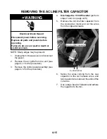
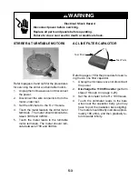
Страница 37: ... from the unit see page 4 11 for the procedure 3 Remove the control panel assembly see page 4 12 for the procedure 4 Discharge the 1100 W inverter perform steps 3 and 4 on page 4 20 5 Remove the AC line filter capacitor from the cooling fan motor and cut the wires from the capacitor leads AC Line Filter Capacitor Cut Both Wires 6 Splice the wires coming from the new capacitor to the cut harness wi...

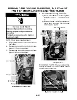
Страница 38: ...trol panel assembly see page 4 12 for the procedure NOTE Sharp edges may be present 4 To remove the cooling fan motor a Press out on the top side locking tabs lift the fan and pull it forward to remove it b Disconnect the 2 wire fan motor con nector from connector CN153 on the 40 W inverter board Line Fuseholder Cooling Fan Motor Exhaust Fan Thermostat Located Behind Control Panel 40 W Inverter Bo...

Страница 39: ...crewdriver blade turn the thermostat so the flange is over the top of the tab and lift the thermostat body out of the mounting hole 6 To remove the line fuseholder a Disconnect the wire connectors from the fuseholder terminals b Remove the fuse from the fuseholder Wire Connectors Press Tab Down Turn Lift Exhaust Fan Thermostat Wire Connectors Line Fuse Fuseholder Screw c Removethescrewfromthefuseh...

Страница 40: ...ock WARNING 1 Unplug the microwave oven or disconnect the power 2 Remove the air grille from the unit see page 4 11 for the procedure 3 Remove the control panel assembly see page 4 12 for the procedure NOTE Sharp edges may be present 4 To remove the exhaust motor start ca pacitor remove the phillips screw and disconnect the wire connectors from the terminals Located Behind Control Panel 40 W Inver...

Страница 41: ...4 19 6 To remove the 40 W inverter board a Disconnect the wire connectors from CN1 CN151 CN152 CN153 b Raise the two top locking arms and remove the inverter board Locking Arms CN1 CN151 CN152 CN153 ...

Страница 42: ...the leads to the two discharge points on the 1100 W inverter Becarefulnottotouchthebare resistor leads during this procedure Exhaust Motor Start Capacitor Red Wht Magnetron Thermostat Blu Gry Line Fuseholder Brn Red Org Screw Screw 9 Pull the front mounting panel out the front of the unit then remove the wires from the side of the panel Remove Wires Front Mounting Panel Front Mounting Panel Discha...

Страница 43: ...locking arm on the 3 wire cable at CN701 and disconnect it 15 Remove the mounting screw from the board and unsnap the 1100 W inverter from the holder Cover Slot 16 Remove the screw and nut from the green ground wire and remove the wire from the 1100 W inverter 12 Remove the top and bottom mounting screws from the 1100 W inverter holder Slide the holder to the right so the slot is over the tab at t...

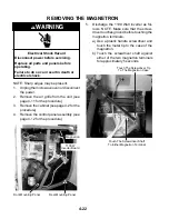
Страница 44: ...ol panel assembly see page 4 12 for the procedure NOTE Sharp edges may be present Magnetron 1100 W Inverter Board Front Mounting Panel Rear Mounting Panel 5 Discharge the 1100 Watt inverter as fol lows NOTE Make sure that the screw driver touches ground before touching the magnetron terminals a Use a plastic handle screwdriver and touch the metal tip to the case of the magnetron b Touch the screwd...

Страница 45: ...stall the magnetron insert the alignment pins into their holes at the back of the magnetron Filament Wires Magnetron Screw 1 of 4 Front Panel 6 Remove the screw from the front mount ing panel 7 Bend the metal tab back then slide the two rear mounting panel tabs toward the right side and lower them through the cutouts in the chassis Front Mounting Panel Screw Rear Mounting Panel Tabs Lower The Rear...

Страница 46: ... for the procedure NOTE Sharp edges may be present Secondary Interlock Switch Monitor Switch 2 Blue N O White COM Brn Yel N C 6 Toremovetheprimaryinterlockswitch a Grip the top and bottom of the linking rod with your fingers and carefully pull backontheswitchessothattheyspring to their fully retracted position Red Wht N O Org Yel COM Linking Rod 5 To remove the secondary interlock switch or the mo...

Страница 47: ... performing step 6 be sure to hook the plastic tabs at the top and bottom of the switch holder into the slotted metal retainers in the chassis as shown below Make sure that the metal retainers are not bent up so that the tabs will not fit into them Otherwise the switches may not operate properly 2 After installing the switch assembly rotate the linking rod and two switches to their forward positio...

Страница 48: ...nplug the microwave oven or disconnect the power NOTE Sharp edges may be present Electrical Shock Hazard Disconnect power before servicing Replace all parts and panels before operating Failure to do so can result in death or electrical shock WARNING Screws Turntable Motor 4 Remove the bottom cover from the micro wave oven see page 4 3 for the proce dure 5 Remove the screws from the turntable motor...

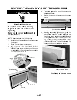
Страница 49: ...e operating Failure to do so can result in death or electrical shock WARNING 6 Starting at the top right corner see the round inset photo in the left column pry the choke cover out with a putty knife and unsnap it from the choke Only remove the top bottom and right sides of the choke cover at this time You will remove the handle end of the choke cover later Choke Cover Choke Door Frame 4 Place the...

Страница 50: ...ife and pry the latching tabs of the choke out of the door frame slots Lift the choke as you release the tabs so they do not snap back into the slots NOTE When you reach the handle side of door pull both the choke and the choke cover away from the door frame and then separate the two components Tab Putty Knife Pry Out REASSEMBLY NOTE When you reinstall the door on the oven insert the top pin into ...

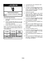
Страница 51: ... Closed Discharge the 1100 W inverter before conduct ing any of the following tests perform steps 1 through 4 on page 4 20 All operational checks using microwave en ergy must be done with the microwave oven loaded with a minimum of 275 ml 9 3 oz of water in a microwave safe container 5 Touch the ohmmeter leads to the termi nals of the monitor switch normally closed Themetershouldindicateaclosed ci...

Страница 52: ...igator clips over contacts 5 and 17 of the ribbon cable b Touch the alligator clips with the test leads c Press the BEVERAGE keypad The meter should indicate a resistance of approximately 200 Ω WARNING Electrical Shock Hazard Disconnect power before servicing Replace all parts and panels before operating Failure to do so can result in death or electrical shock RIBBON CABLE 7 8 9 10 11 12 13 14 3 4...

Страница 53: ...r the procedure for servic ing the AC line filter capacitor 1 Unplug the microwave oven or disconnect the power 2 Discharge the 1100 W inverter perform steps 2 through 4 on page 4 20 3 Set the ohmmeter to the R x 1000 scale 4 Touch the ohmmeter leads to the bare wires near the capacitor body you may have to pull the insulation back slightly The meter should briefly indicate approxi mately 10K ohms...

Страница 54: ... indicate an infinite circuit WARNING Electrical Shock Hazard Disconnect power before servicing Replace all parts and panels before operating Failure to do so can result in death or electrical shock Refer to page 4 4 for the procedure for servic ing the humidity sensor 1 Unplug the microwave oven or disconnect the power 2 Disconnect the 3 wire connector from the control board 3 Set the ohmmeter to...

Страница 55: ...uit 0 Ω 4 To test the exhaust fan thermostat a Disconnect the wires from the termi nals b Touch the ohmmeter leads to the ter minals The meter should indicate an open circuit infinite NOTE The ther mostat closes 140 F 60 C and will reset open 104 F 40 C Refer to page 4 18 for the procedure for servic ing the exhaust motor start capacitor 1 Unplug the microwave oven or disconnect the power 2 Discha...

Страница 56: ... wire in the fan con nector and the black wire to the black wire in the fan connector Refer to page 4 10 for the procedure for servic ing the hood exhaust fan motor 1 Unplug the microwave oven or disconnect the power 2 Disconnect the hood exhaust fan motor connector from the main harness connec tor 3 Set the ohmmeter to the R x 1 scale 4 Touch the meter leads to the motor termi nals The ohmmeter s...

Страница 57: ...gnetron 1 Unplug the microwave oven or disconnect the power 2 Discharge the 1100 W inverter perform step 5 on page 4 22 3 Disconnect the wire connectors from the filament terminals 4 Set the ohmmeter to the R x 1 scale 5 Touch the ohmmeter leads to the filament terminals The meter should indicate less than 1 Ω 6 Touch one ohmmeter lead to the chassis and the other to each of the filament termi nal...

Страница 58: ...e cabinet and separate the wires 3 Connect an ammeter clamp around the white power cord wire 4 Turn the microwave oven On 5 Check the ammeter for a 15A reading If the ammeter indicates more than 0 5 amps check the magnetron and its wiring If the ammeter indicates less than 0 5 amps it indicates that there is no input to the 1100 W inverter Check for the following No AC voltage supply or control si...

Страница 59: ...ation due to overheating NOTE Refer to the Warnings on page 1 7 Do not attempt to repair or make any adjust ments to the inverter board Check Wiring 1 Unplug the microwave oven or disconnect the power 2 Discharge the 1100 W inverter perform steps 2 through 4 on page 4 20 3 Visually inspect inverter board connectors CN701 CN702 CN703 andE701 Check for signs of failure due to loose wiring unseated c...

Страница 60: ...s 1 and 2 of connector CN152 refer to the photo on the previous page The meter should indicate 12 volts DC 7 Close the oven door 8 Press the LIGHT keypad on the control panel and set the lights to full intensity NOTE Do not press the LIGHT keypad during the measurement 9 Touch the voltmeter test probes to pins 3 and 4 of connector CN152 The meter should indicate 12 volts DC 10 Press and release th...

Страница 61: ...der Load Display Likely Failure Condition Recommended Repair Procedure Flashing colon Power Failure After a power failure the colon will be flashing Press any key to end this indication The colon will then be steady when in standby F2 Keyboard Failure Replace membrane switch If problem persists replace control system assembly F3H Humidity Sensor Failure Connect a new sensor to the board at P5 If n...

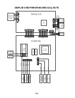
Страница 62: ...5101 DISPLAY PCB POWER PCB Ribbon Cable 3C Red Green MCU 1 P12 1 P14 P2 1 CN701 Black Red White Humidity Sensor P5 1 Touch Panel Membrane Switch P6 1 1 Ribbon Cable 4C P3 CN151 1 40W Inverter 1 P11 P21 P11 P21 Magnetron Thermostat TT Motor Stirrer Motor 1100W Inverter Orange Interlock Secondary Switch Fuse 0 25 Amp Orange Fuse 4 Amp Fuse 4 Amp ...

Страница 63: ...y checks only DOOR CLOSED DOOR OPEN Switch Test Procedure Door Open Door Closed 1 Disconnect the wires at the primary interlock switch 2 Check from the common terminal blue black wires to the normally open terminal white wire 1 Disconnect the wires at the secondary interlock switch 2 Check from the common terminal orange yellow wires to the normally open terminal red white wires 1 Disconnect the w...

Страница 64: ...eypad as shown in the Key Table to the right As you do the number 8 should appear in the display position shown in the chart to indicate that the circuits are complete and that the re lays are working properly NOTE If you should press the OFF CANCEL keypad during any of the tests you will exit the test mode Perform step 2 to reenter the test mode Key Name Function Display Position POPCORN 5 BAKED ...

Страница 65: ...GR22 P0 P10 P11 WIRE TO WIRE CONNECTORS 1 HL 1 HL HL 21 W22 22 Y22 2P11 50 GR16 41 Y G18 43 Y G18 GND 42 Y G18 CN1 CN152 CN151 P5 1 P2 4903 MW Relay 50 GR16 1 2 1 CN153 CL CN703 E701 45 26AWG 4C 46 26AWG 3C SYMBOL NOTES CONDITION DOOR OPEN CF TT CAVITY LAMP D C COOLING FAN MOTOR TURNTABLE MOTOR CL B BLACK BL BLUE R RED W WHITE G GREEN Y YELLOW BR BROWN OR ORANGE HF HOOD EXHAUST FAN MOTOR SM STIRRE...

Страница 66: ...CONNECTOR BLACK BROWN YELLOW INTERLOCK SECONDARY SWITCH INTERLOCK MONITOR SWITCH INTERLOCK PRIMARY SWITCH INTERLOCK SUPPORT RED 1 2 4903 MW RELAY 4906 4901 1 P12 YELLOW P5 P3 P2 L V T TR1 5101 DISPLAY PCB POWER PCB GREEN MCU BLUE RED GRAY 1 P14 WHITE RED WHITE DC COOLING FAN MOTOR BLACK RED RED BLUE RED GRAY ORANGE WHITE BROWN RED RED RED BLUE RED BLUE BLACK BROWN BLACK BROWN GRAY BLACK WHITE RED ...

Страница 67: ...7 3 STRIP CIRCUITS MICROWAVE COOKING BLOWER FAN ON AUTOMATIC BLOWER FAN ON VARIABLE ...

Страница 68: ...7 4 COOKTOP LAMP ON VARIABLE LIGHT MICROWAVE TIME OF DAY DISPLAYED DOOR OPEN CAVITY LAMP ON ...

Страница 69: ...7 5 NOTES ...

Страница 70: ...7 6 NOTES ...

Страница 71: ...R READY TO IDENTIFY YOU AS AN AUTHORIZED SERVICER FOR LITERATURE ORDERS PHONE 1 800 851 4605 IN CANADA FOR PRODUCT SPECIFICATIONS AND WARRANTY INFORMATION CALL 1 800 461 5681 FOR TECHNICAL ASSISTANCE WHILE AT THE CUSTOMER S HOME CALL THE TECHNICAL ASSISTANCE LINE 1 800 488 4791 HAVE YOUR STORE NUMBER READY TO IDENTIFY YOU AS AN AUTHORIZED SERVICER FOR WHIRLPOOL PRODUCTS 1 800 253 1301 FOR KITCHENA...

Страница 72: ...CORPORATION ...

Отзывы: