4-20
REMOVING THE 1100 W INVERTER BOARD
Electrical Shock Hazard
Disconnect power before servicing.
Replace all parts and panels before
operating.
Failure to do so can result in death or
electrical shock.
WARNING
NOTE:
Sharp edges may be present.
1.
Unplug the microwave oven or disconnect
the power.
2.
Remove the control panel assembly (see
page 4-12 for the procedure).
3.
Remove the cooling fan motor (see page
4-16 for the procedure).
NOTE: Make sure to read the “Warnings” on
page 1-7 before you continue.
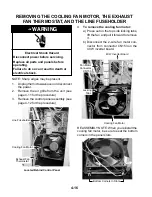
4.
Hold a 20,000
Ω
(red-black-orange)
2-Watt resistor by the body with a pair of
long nosed pliers, and touch the leads to
the two discharge points on the 1100 W
inverter.
Be careful not to touch the bare
resistor leads during this procedure.
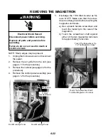
Exhaust
Motor
Start
Capacitor
(Red &
Wht)
Magnetron
Thermostat
(Blu & Gry)
Line
Fuseholder
(Brn, Red,
& Org)
Screw
Screw
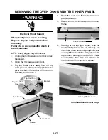
9.
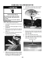
Pull the front mounting panel out the front
of the unit, then remove the wires from the
side of the panel.
Remove
Wires
Front Mounting Panel
Front
Mounting
Panel
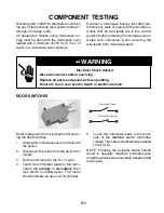
Discharge Points
5.
Remove the 40 W Inverter Board (see
page 4-19 for the procedure).
6.
Remove the exhaust fan thermostat (see
page 4-17 for the procedure).
7.
Disconnect the red and white wires from
the exhaust motor start capacitor, the blue
and gray wires from the magnetron ther-
mostat, and the brown, red, and orange
wires from the line fuseholder terminals.
8.
Remove the two screws from the front
mounting panel.
Содержание GH9185XL
Страница 67: ...7 3 STRIP CIRCUITS MICROWAVE COOKING BLOWER FAN ON AUTOMATIC BLOWER FAN ON VARIABLE ...
Страница 68: ...7 4 COOKTOP LAMP ON VARIABLE LIGHT MICROWAVE TIME OF DAY DISPLAYED DOOR OPEN CAVITY LAMP ON ...
Страница 69: ...7 5 NOTES ...
Страница 70: ...7 6 NOTES ...
Страница 72: ...CORPORATION ...

