4-25
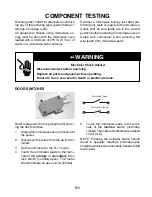
d) Carefully unhook the two locking arms
and pull the switch off the two pins.
e) Remove the wire connectors from the
switch terminals.
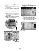
T10 Torx
Screws
White (N.O.)
Blu-Blk (COM)
Primary Interlock Switch
b) Use a T10 torx screwdriver and remove
the two screws from the interlock switch
assembly.
c) Pull the switch assembly away from the
front chassis and position it so that you
can access the primary interlock switch.
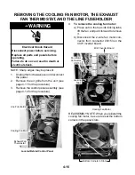
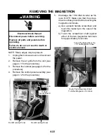
REASSEMBLY NOTES:
1.
When reinstalling the switch assembly
after performing step 6, be sure to hook
the plastic tabs, at the top and bottom of
the switch holder, into the slotted metal
retainers in the chassis, as shown below.
Make sure that the metal retainers are not
bent up so that the tabs will not fit into
them. Otherwise, the switches may not
operate properly.
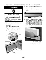
2.
After installing the switch assembly, rotate
the linking rod and two switches to their
forward
position (see the photos in step
6a). Close and open the door several
times to make sure that the switches oper-
ate normally. If not, check step 1 above for
proper installation, as well as the forward
position of the switches.
Switch
Holder
Tab
Metal
Retainer
Slot
Pin
Locking Arm
Содержание GH9185XL
Страница 67: ...7 3 STRIP CIRCUITS MICROWAVE COOKING BLOWER FAN ON AUTOMATIC BLOWER FAN ON VARIABLE ...
Страница 68: ...7 4 COOKTOP LAMP ON VARIABLE LIGHT MICROWAVE TIME OF DAY DISPLAYED DOOR OPEN CAVITY LAMP ON ...
Страница 69: ...7 5 NOTES ...
Страница 70: ...7 6 NOTES ...
Страница 72: ...CORPORATION ...


