5-9
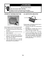
CN701
(I/O Signal)
CN702
(120 VAC)
E701
(Ground)
CN703
(High Voltage Output
To Magnetron)
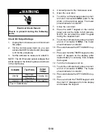
40 W INVERTER
Refer to page 4-18 for the procedure for servic-
ing the 40 W inverter.
CN1 (120 VAC Input)
CN151 (Signal Input)
CN153 & CN152 (12 VDC)
Check Wiring
1.
Unplug the microwave oven or disconnect
the power.
2.
Visually inspect inverter board connectors
CN1, CN151, CN152, and CN153. Check
for signs of failure due to loose wiring,
unseated connectors, and discoloration
due to overheating.
NOTE: Refer to the “Warnings” on page 1-7.
Do not attempt to repair, or make any adjust-
ments to the inverter board.
Check Wiring
1.
Unplug the microwave oven or disconnect
the power.
2.
Discharge the 1100 W inverter
(perform
steps 2 through 4 on page 4-20).
3.
Visually inspect inverter board connectors
CN701, CN702, CN703, and E701. Check
for signs of failure due to loose wiring,
unseated connectors, and discoloration
due to overheating.
Continued on the next page.
Electrical Shock Hazard
Disconnect power before servicing.
Replace all parts and panels before
operating.
Failure to do so can result in death or
electrical shock.
WARNING
Содержание GH9185XL
Страница 67: ...7 3 STRIP CIRCUITS MICROWAVE COOKING BLOWER FAN ON AUTOMATIC BLOWER FAN ON VARIABLE ...
Страница 68: ...7 4 COOKTOP LAMP ON VARIABLE LIGHT MICROWAVE TIME OF DAY DISPLAYED DOOR OPEN CAVITY LAMP ON ...
Страница 69: ...7 5 NOTES ...
Страница 70: ...7 6 NOTES ...
Страница 72: ...CORPORATION ...


