background image

Quick Start - page  21

LXE / Feb 2018

Q U I C K   S T A R T   G U I D E

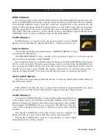
SET Button on Monitor 1 Module

Allows setting Sources to the EXT Destinations.  Used in Conjunction with the Rotary 

Encoder Source Select above it.

Ext 1 and Ext 2 on Monitor 1 Module

Use to assign Ext 1 or 2 to the Monitor1.

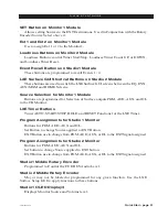
Loudness Buttons on Monitor 2 Module

Loudness Buttons control Timer Start/Stop, Loudness Timer Count UP, or DOWN, 

and Loudness Timer Reset.

Event Recall Buttons on Studio 1 Module

These buttons are programmed to recall Events 1- 4.

LXE Surface GUI Shortcut Buttons on Studio 2 Module

These buttons are used to switch the LXE Surface GUI screens between the EQ, DYN, 

AUX/MXM and HOME Screens.

Source Selection for Monitor 1 Module

Buttons are programmed for Selection of Surface outputs PGM, AUD, AUX, and OL 

to the CR Monitor.

LXE Timer Buttons

Timer AUTO, START/STOP, HOLD and RESET Functions for the LXE Timer.

Program Assignments for Studio 1 Monitor

Buttons for PGM, AUD, AUX and OL.

Set Button to change Source applied to EXT Button.

EXT Button use to change from PGM, AUD, AUX, or OL to the EXT Signal assigned.

Program Assignments for Studio 2 Monitor

Buttons for PGM, AUD, AUX and OL.

Set button to change Source applied to EXT button.

EXT Button use to change from PGM, AUD, AUX, or OL to the EXT Signal assigned.

Studio 1 Middle Rotary Encoder

Programmed to Control the CUE BUS Audio Level.

Studio 2 Middle Rotary Encoder

May or may not be labeled or programmed for any given function. Use the LXE 

 Surface Setup GUI to apply functions to these buttons.

Studio 1 OLED Display 3

Displays Monitor Source and Volume level.

Содержание LXE 13

Страница 1: ...LXE 600 Industrial Drive New Bern North Carolina USA 28562 Digital Control Surface Quick Start Guide WheatNetIP LXE Surface Setup GUI 1 6 3 and higher...

Страница 2: ...ongoing operations and event recall allows painless one touch console reconfiguration at the press of a button With its inherent control flexibility and ability to access thousands of signals sources...

Страница 3: ...led holes have been provided so that screws may be used to mount the surface securely to the countertop Locate the LXE on the counter and remove the screws two per module that hold the second and next...

Страница 4: ...UNTER 3 3 8 3 3 8 3 3 8 3 3 8 52 1 16 33 POS FRAME 58 1 16 37 POS FRAME 70 1 8 45 POS FRAME 22 21 32 33 POS FRAME 25 21 32 37 POS FRAME 31 11 16 45 POS FRAME 22 21 32 33 POS FRAME 25 21 32 37 POS FRAM...

Страница 5: ...ME 13 27 32 9 POS FRAME 37 31 32 25 POS FRAME 44 29 POS FRAME shown on drawing 50 1 16 33 POS FRAME 56 1 16 37 POS FRAME 68 1 8 45 POS FRAME CUTOUT DIMENSIONS 5 POS FRAME 8 1 16 x 18 1 2 9 POS FRAME 1...

Страница 6: ...e the other cable to connect the second power supply to the remaining control surface power supply connector The LXE control surface is powered by a Wheatstone Model PS 1600 rackmount power supply Thi...

Страница 7: ...can be mounted to the counter for your convenience and a 3 pin JST plug that plugs into the Panel Host board PH12 LXE PH8 LXE PH4 LXE There are several RJ 45 connectors on the rear of the LXE control...

Страница 8: ...hical User Interface GUI program intended to be straightforward in use with controlling and displaying graphics production tools and set up screens The LXE HDMI monitor is divided into several section...

Страница 9: ...or the four Aux Master outputs and the Mix Minus Outputs X Y Router Button Opens up the XY router screen Input Button Displays interactive Source Mode Phase Pan and Aux Send settings for the selected...

Страница 10: ...ternally and to its associated host therefore no IP configuration is required for the LXE Surface TheLXEsurfaceHostwillcomeconfiguredwithadefaultIPaddressof192 168 87 90 To changethe IPaddress to some...

Страница 11: ...Quick Start page 10 LXE Feb 2018 Q U I C K S T A R T G U I D E LXE Modules...

Страница 12: ...ast With this said we should point out that when we build your LXE at the factory it will be pre programmed with the most basic functions so that you don t have to spend hours learning the custom part...

Страница 13: ...t the top that has been factory configured to be a X Controller Rotating the encoder allows you to look through the list of available sources Press the encoder to TAKE the selected source Taking the s...

Страница 14: ...ow followed by descriptions for each of the functions Channel Select Theinputfadernumberforwhichthesetbuttonispressedisdisplayedhere Youmay also navigate to other input fader by clicking on the grey C...

Страница 15: ...ecially useful in large systems with many sources This is described in the LXE Surface Setup GUI section Mode Button Each Input Module has a MODE Button Use this button to quickly change the input fad...

Страница 16: ...ff to indicate that the source is no longer assigned to that bus The OL Bus The OL bus has a special function in relation to a channel s Bus Minus output Each signal that can be assigned to a channel...

Страница 17: ...hat includes all active faders on its selected source bus except for itself These auto generated mix minus signals may be routed to feed telephone hybrids remote operator feeds or other devices as req...

Страница 18: ...in the LXE Surface Setup GUI The switch LED lights to indicate the channel is ON and the ON AIR LED will light on the meterbridge if configured in the Surface VDips Channel OFF Button The channel OFF...

Страница 19: ...e top of each module In this guide we will describe the controls and functions of these modules as a group starting from the top of the modules and going down Rotary Encoder This encoder is programmed...

Страница 20: ...ute input fader strips to MIX MINUS busses Press the SET button on any channel If that channel is assigned to feed an MXM bus the corresponding MXM ASSIGN switch and OLED indicator on the fader strip...

Страница 21: ...einputsaredisplayedintheOLEDDISPLAY2 display for the selected channel When the desired input source is scrolled into the SOURCE win dow pressing the TAKE button will cause that source to be programmed...

Страница 22: ...Monitor1 Module Buttons are programmed for Selection of Surface outputs PGM AUD AUX and OL to the CR Monitor LXE Timer Buttons Timer AUTO START STOP HOLD and RESET Functions for the LXE Timer Program...

Страница 23: ...R T G U I D E Studio 2 OLED Display3 Displays Monitor Source and Volume level Studio TB and Dim Buttons on Studio1 and 2 Modules TB Switch puts TB Source into the Studio 1 Monitor Destination DIM Swi...

Страница 24: ...If this button is not lit while in SET MODE on the Input module the Dynamics parameters are NOT applied to the Input module COMP Activates the Compressor controls on the EQ DYN module COMP IN Enables...

Страница 25: ...onal module is the SW24 for the LXE surface It contains 3 Banks of 8 buttons each for a total of 24 Programmable Buttons These buttons are configured in the LXE Surface Setup GUI For more details on s...

Страница 26: ...e when the signal level is approaching a clipping distorted level The next ten LEDs are yellow indicating a normal level range and the remaining LEDs are green The top member of the pair indicates the...

Страница 27: ...1 ans 2 Destinations Clocks and Timers Program Meters Loudness Meters Navigation Buttons Custom Names applied in the LXE Surface Setup GUI Current Running Event Meter Labels AUX and Mix Minus Send Me...

Страница 28: ...lled from the Events Manager Current Event Last event taken Event Recall Select from available events To load an event select from the list click Arm then Take Click UNDO to go back to the Previously...

Страница 29: ...e 0n Controls Select the appropriate buttons to allow the Mix Minus busses to be either Pre Fader Pre ON or BOTH AUX MXM Button selected AUXMASTERSSection Separate ON OFF and Master volume for each Au...

Страница 30: ...r Screen TAKE Button to execute a route change X Y ROUTER Button selected DESTINATIONS Section List of Destinations signals based on vis ibilitiessetintheSurfaceSetupGUI SOURCES Section List of Source...

Страница 31: ...to Mix Minus bus Channel Select Shows Channel Selected into SET MODE LXE Input Screen Input Button selected Source Shows Source Label assigned to selected input fader module Aux Bus Assignment Assign...

Страница 32: ...selecting parameter and moving bar in the graph using mouse on screen fader or touchscreen gestures Dynamics Button selected VU Meters Indicate input gain to the processor GR Meters Indicate Gain Red...

Страница 33: ...lter ON or OFF HPF Frequency Selection Click to change the HPF Frequency Point BAND Selections Used to Select EQ Frequency Octave and dB boost or cut levels LPF OUT Low Pass Filter Select to turn ON o...

Страница 34: ...ected fader Preset Shows currently loaded preset if any Recall a Preset Select from the list of saved presets and apply to currently selected input fader or all input faders Modify Rename and or Delet...

Страница 35: ...LX E Feb 2018 Quick Start page 34 LXE Custom Screen Use this button to load Custom Screen Builder screens to the LXE Surface GUI...

Страница 36: ...d ensure the Surface Host Network Interface is connected to the Wheatnet IP Switch From the factory your surface will have an IP address of 192 168 87 90 For the initial setup and to allow the Surface...

Страница 37: ...Surface Setup GUI Locate the Install Package from the shipped media or download Double Click the WnetIP_LXE_Surface_Setup_GUI_X_XX_X exe where X repre sents the version of the software to start the In...

Страница 38: ...Quick Start page 37 LXE Feb 2018 Q U I C K S T A R T G U I D E Click Next to Install the Selected Components Verify the installation directory Click Install to continue...

Страница 39: ...en the Installation steps are completed click Close to finish and close the installer Launch the LXE Surface Setup GUI When you launch the LXE Surface Setup GUI you will be present with this screen Fo...

Страница 40: ...your installation When you select this option the LXE Surface Setup GUI scans the networks that the PC is connected to for LXE Surface Hosts Select the Undefined Surface and click Finish If the applic...

Страница 41: ...if Engine Host Blade has not been associated with the surface or the Blade s ID and IP address have changed we will need to make that association here in the GUI First we should verify that the Module...

Страница 42: ...one in the available pane to place it in the Surface panels pane Check the box Allow Device Changes This will allow you to do customizations later on and allow us to make changes for initial setup pur...

Страница 43: ...ou will only see the LXE Devices in the Locator results In our example below we are using the main WheatNet IP network as you can see other devices in the list Find in the list and click on the LXE Su...

Страница 44: ...hift or CTRL key and click the appropriate module panel hosts Once you have selected all of the Module Panels in the Set all Selected Devices panel below drop the Host Data selector down and scroll to...

Страница 45: ...gain Select Synch from Surface and select the Surface from the list Once connected you will be on the Module Layout Tab with a representation of your Surface displayed and the Status in the Status Bar...

Страница 46: ...the network we can now associate the surface with its Engine Blade Todothis opentheLXESurfaceSetupGUI application and connect to your Surface as in previous steps Once connected and your surface layou...

Страница 47: ...e Apply Button in the bottom right hand corner of the LXE Surface Setup GUI Status bar Youwillreceiveapopup message stating that all of the configuration files on the surface will be overwrit ten woul...

Страница 48: ...screens For the X controller you can set the visibilities on Channel 1 If you want to repeat those same visibilities right click on Channel 1 and select Copy Right click again and select Paste All Th...

Отзывы: