background image

58 


the  caller  on  the  other  channel.  The  easiest  method  to  do  this  is  to 
dedicate PGM 3 for call recording. 

To use the “PGM 3 method” you’ll want 

the host mic on a second fader 

channel, so the original channel is still available to feed air. Typically, the 
mic  is  also  assigned  to  channel  7  (or  15)  and  the  phone  is  assigned  to 
channel  8  (or  16).  Assign  the  mic  and  phone  channels  only  to  PGM  3

making sure no other channels are assigned to PGM 3. Use 

Navigator

 to 

connect  PGM  3  to  the  call  recorder  output.  Use  the  Advanced  Channel 
Feature 

Pan

 to pan the mic channel fully to the left channel and pan the 

phone channel fully to the right channel. The caller audio is now separated 
from the talent audio and each channel of the recording can be individually 
edited on the call recorder.  

The  advantage  o

f  using  the  “PGM  3 

method

”  is  that  it

  allows  the  call 

recorder  to  connect  via  Ethernet,  using  WNIP  drivers,  or  by  using  any 
stereo analog or digital output. It also means the call recorder can  easily 
be  set  to  record  stereo  programming.  These 

“Telco  Record” 

channel 

sources  and  pan  settings  can  be  saved  as  an  Event  to  quickly  reset  the 
console for call recording by recalling that Event. 

If  you  don’t  have  a  spare  channel  for  a  second  mic,  and  are  using  an 

analog phone hybrid, then you could use two Y cables, one on the phone 
hybrid  and  the  other  on  the  console  output  that  connects  to  the  phone 
hybrid. One channel will be the caller audio while the other will be the mix-
minus  going  back  to  the  caller  (e.g.,  the  talent  mic  audio).  If  the  call 
recorder

’s

  analog  input  is  not  balanced,  a  balanced-to-unbalanced  balun, 

or a matchbox, will need to be used. 

Going Live-to-Air 

When a caller or remote will go live-to-air, their 

PGM 1

 and 

Cue

 buttons 

should  be  assigned.  When  their  channel  is  off  the  caller/remote  will hear 
the  Off  Line  bus  (any  channel  assigned  to  PGM4/OL  minus  their  own 
channel). Typically, only the board operator mic is assigned to PGM 4/OL, 
but you may need a producer mic assigned as well. This allows the board 
operator (and producer) to talk with the caller/remote to prepare them for 
going live-to-air. 

When  the  caller/remote  channel  is  turned  on,  their  mix-minus  audio 

switches  so  they  hear  everything  assigned  to  PGM  1  (minus  their  own 
audio) so they can interact accordingly. If the board operator needs to talk 
to  the  caller/remote  while  they

re  on-air,  they  press  the  momentary 

TB


button on the caller/remote channel to give them cues (a break is coming 
up,  etc.).  This  action  interrupts  the  return  audio  so  using  TB  while  live 
should  be  used  sparingly,  and  certainly  not  while  the  caller  or  remote  is 
talking. 

RAZOR I/O INTERFACE 

Razor I/O Interfaces are 1RU rack mount devices installed in the studio 

and/or TOC (Technical Operations Center) to connect additional peripheral 

equipment with the DMX console and other devices on the WNIP network. 
Each  Razor  has  eight  stereo/16  mono  inputs  and  eight  stereo/16  mono 
outputs.  A  Razor  is  often  used  to  interconnect  satellite  receivers,  tuners, 
phone  hybrids,  codecs,  internet  streamers,  air  chain  processor,  and 
recorders with the DMX console.  

Their input signals often appear as sources on DMX fader channels while 

their outputs may be connected to console PGM buses or to channel bus-
minus  signals.  If  you

re  checking  for  levels,  engineering  should  have 

supplied  a  list  of  the  input  and  output  signals  on  each  Razor  so  you  can 
confirm  whether  a  specific  signal  is  present  since  that  is  the  biggest  use 
for the Razor front panel display by a board operator. 

The Razor’s front panel has the same 

type OLED display and large knob 

rotary encoder as used on the DMX fader channels. Rotate the encoder to 
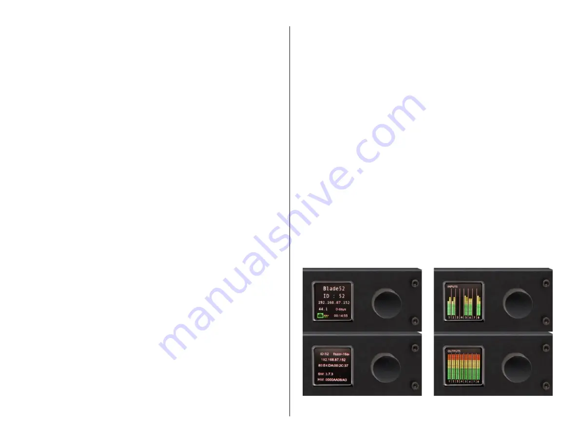
switch the display between four screens: Input Levels, Output Levels, and 
two  screens  displaying  technical  details  on  that  Razor  (name,  ID#,  IP 
address,  sample  rate,  MAC  address,  software  revision,  and  hardware 
revision). The four screens are shown in Figure 4-16. 

The  two  screens  of  interest  to  board  operators  are  the  Inputs  and 

Outputs screens. Unlike the DMX console meters these displays only show 
average levels using  vertical bar graphs since they are mainly to  confirm 
there is a signal present and its level appears 

normal.


The Inputs display, in Figure 4-16, shows normal signal levels where all 

the green and a few yellow segments are lit up. Three inputs (3, 4, and 7) 
have  no  audio.  The  Outputs  display  shows  a  test  tone,  set  for  the 
maximum signal level, being fed to all eight stereo outputs which lights up 
all  meter  segments.  In  practice,  both  Inputs  and  Outputs  levels  would 
appear like the levels shown in the Inputs display. 


Figure 4-16 Razor Front Panel Displays 

Содержание AUDIOARTS ENGINEERING DMX Series

Страница 1: ...1 Networked AoIP Broadcast Console Manufactured by Wheatstone Corporation ...

Страница 2: ...ademarks of Wheatstone Corporation or its subsidiaries Microsoft and Windows are registered trademarks of Microsoft Corporation All other trademarks and trade names are the property of their respective companies Customer Service Contact Information Wheatstone 600 Industrial Drive New Bern NC 28562 USA For technical support including on site service general product training repair and parts contact...

Страница 3: ...0 Mix Engine Connections 12 DMX Power Up 13 Checking Out the DMX Features 14 Mix Engine Signal Notes 16 Additional DMX Features 17 Razor Interface Notes 19 3 DMX Apps and Console Configuration 20 DMX Surface Setup App 20 The Navigator App 31 Software Updates 44 4 DMX Operation and Applications 46 Console Operation 46 Using the Advanced Channel Features 52 DMX Applications 56 Razor I O Interface 58...

Страница 4: ...4 ...

Страница 5: ...erator access Monitor Controls The console supports a Control Room and an associated Studio with CR monitor CR headphone Cue and Studio Monitor level controls CR and Studio monitor source selectors timer controls and four Console Event buttons Meter Bridge Three stereo LED meters display the levels for PGM 1 PGM 2 and a Switched signal PGM 3 PGM 4 EXT and CUE when enabled The Meter Bridge also has...

Страница 6: ...100 meters The DMX can also be networked with any WheatNet IP Blade to provide additional audio and logic I O To network he DMX with a full WNIP System the configuration of the Mix Engine s built in Ethernet switch which is set for stand alone operation from the factory must be edited See Appendix A on the configuration setting which needs to be changed to support networking the DMX with a larger ...

Страница 7: ...ing the Monitor section S S button Timer Start Stop control or automatically when the Auto Timer button is lit and an audio source set for Timer Reset assigned to specific audio signals using the DMX Surface Setup app is turned on Mix Engine All audio and logic connections are made on the rear of the Mix Engine Figure 1 5 This 1RU device has a 5 port Gigabit switch two high quality low noise Mic P...

Страница 8: ... FSD equivalent to analog 4 dBu Nominal Maximum Input or Output Level 20 dB FSD 0 dB FSD 18 dB of level gain trim control available in Navigator Digital In Digital Out Frequency Response 0 0 dB 20 Hz to 20 kHz 20 dB FSD Digital Input Analog Output THD Noise 0 00017 20 Hz 20 kHz 20 dB FSD Digital I O continued Signal Format AES 3 S PDIF inputs only AES 3 Input Compliance 24 bit uses SRC to support ...

Страница 9: ...ting from abuse careless use misuse improper installation electrical spikes or surges or alteration repair or service of the unit or equipment by anyone other than Wheatstone Corporation or its authorized dealer d This Warranty is void if the serial number has been removed altered or defaced e This Warranty DOES NOT cover loss or damage direct or indirect arising out of the use or inability to use...

Страница 10: ...k on the back of the Mix Engine This constrains are far away the Mix Engine can physically be located since the DC cable must not be under strain when connected between the DMX Surface and Mix Engine Note The in line DC supply used with the DMX 16 Surface Wheatstone 980064 can be used to power a DMX 8 Surface if the Mix Engine must be mounted beyond the reach of the included 16 foot DC cable The D...

Страница 11: ...jack On a DMX 16 Surface or on a DMX 8 that is using the in line supply route the category cable to the Mix Engine and plug it into Port 4 on the ETHERNET switch Plug the in line DC power supply s IEC AC cord into an isolated AC outlet Figure 2 3 Mix Engine Rear Panel Partial View Ethernet and DC Power Connections If not connected already connect the short category cable supplied with the Mix Engi...

Страница 12: ...e standard lengths of straight thru CAT5 cables along with RJ45 Audio Adapters to plug into peripheral device jacks Angry Audio and other vendors make a wide variety of RJ45 Audio Adapters most of which are carried by Audioarts and Wheatstone dealers For more information on RJ45 cable adapters for audio wiring refer to this web page https angryaudio com studiohub Figure 2 4 Audio Logic RJ45 Pin Ou...

Страница 13: ...ted ground circuits orange outlets in the USA which are ideally on a UPS Uninterruptible Power Supply On a DMX 16 plug in the Surface Supply On a DMX 8 or DMX 16 plug the IEC AC cord into the Mix Engine It takes about 90 seconds for each DMX device to boot up connect to the WNIP network and be ready for use If the DMX 16 Surface is powered up without being networked to a Mix Engine or if the Mix E...

Страница 14: ...a stereo input using Navigator As the encoder is turned CW past the Mix Engine s physical input signal names the internal signals within the DMX are listed Many if not most of these signals are typically not set as visible on fader channels but on a new console every source signal is set visible to ease installing and configuring the DMX Setting which signals are visible is set using the DMX Surfa...

Страница 15: ...t set to each of the four PGM DIGITAL outputs which have the same signals as the analog jacks to confirm that each has a 20 dBFS output The default sources connected to the four PGM outputs are the PGM 1 to PGM 4 buses To check the monitor outputs the four OUT jacks connect a test set or a powered monitor speaker with a balanced input to the CR Out jack In the left column of the monitor section se...

Страница 16: ...ike a Henry warning light interface a Mic Arm LED or a CD player Each Logic jack has six LIO logic ports on pins 2 7 plus ground on pin 1 and 5 volts on pin 8 Each logic port is independently assigned using Navigator to function as a logic output like On Tally Studio In Use tally Start Pulse etc or as a logic input like Channel On Channel Off Ready Cue etc Each Mix Engine also has 128 Soft LIO SLI...

Страница 17: ...ttons The Off Line bus is an internal bus that s used solely to create the To Network signal for callers and remotes while their fader channel is turned off When the DMX is configured so the PGM 4 buttons are Off Line buttons they are most often also setup for pre switch and pre fader operation This allows the talent to carry on a hands free conversation with a caller or remote while they are not ...

Страница 18: ...e then click the encoder to assign the highlighted source to the blinking button which then stops blinking Two sources can be assigned to the Studio EXT button one is set while the button is lit the other is set while it s unlit Press hold the unlit EXT button until it blinks about three seconds to set the unlit button source Likewise press hold the lit EXT button for about three seconds until it ...

Страница 19: ...within the system with no connection limitations 2 Although the eight output jacks can also be setup for 16 mono destinations because the Razor only receives eight simultaneous audio streams this can restrict the total number of simultaneous mono signals that Razor can receive depending upon their sources If each mono source comes from a different Blade which is not likely you could only receive e...

Страница 20: ... on page 11 We recommend setting the PC s Network Interface Card NIC to 192 168 87 21 with a subnet mask of 255 255 255 0 This puts that PC on the same subnet as the Mix Engine its default IP address is 192 168 87 101 and its name is Blade01 and the DMX Surface its default IP address is 192 168 87 201 and its name is Surf01 To ensure the apps install properly right click on the installer icon or i...

Страница 21: ...ndow Once Finish appears in lieu of Cancel click it to close the System Scan window A save system info dialog pops up Click Yes to save the system information A Save File dialog box opens showing the default save location Click Save then Yes to save the sysinfo wnsi3 data file which saves your system information to the PC The System Info pane at the right side of the app window will now be populat...

Страница 22: ...nges Clicking No discards all changes made on the previous tab since the last time Apply was clicked Figure 3 5 Apply Changes Warning Pop Up Note We recommend unchecking Do not show this warning again during this session before clicking Yes or No so that you keep getting the popup If left checked the popup no longer appears but the default selection is No which means if you switch to a new page ta...

Страница 23: ...ne to 59 must pass after a Surface control was last touched before the OLED displays switch from the Normal Level to the AutoDim Level The default setting is 10 which means that after no Surface control has been touched for ten minutes the OLED displays automatically dim down to the AutoDim Level When an operator touches any control the dimmed OLED brightness umps back to the Normal Level Note Set...

Страница 24: ...e checked to allow the board operators to freely turn any bus assignment button on off as required Unchecking one or more Allow PGM Bus Assign selections and then clicking Apply means the PGM button settings as currently set on the console cannot be changed by a board operator This might be done for consoles that serve dual purposes like simultaneous on air and network origination The PGM buttons ...

Страница 25: ...hat signal and displays its current logic settings in the seven assignment sections on the right half of the page tab These settings can then be edited as required To see hear the effect of the new selections click Apply to transmit the updated settings to the DMX Surface Note Before adding your signals to the Signals list run a System Scan see Setting the Surface Host section on page 21 The signa...

Страница 26: ... typically assigned the same for all signals although some users only enable this feature on microphones Fader Cue This setting is like EFS in that fader movement affects channel status When checked moving the fader to full off turns cue on and moving the fader away from full off turns cue off This action emulates a feature found on analog consoles with rotary volume controls which put the channel...

Страница 27: ...cally only microphones are set to mute outputs For mics located in the Control Room both the CR and Cue outputs are typically checked muted For mics located in a Studio typically only the Studio output is checked muted unless cue is fed to the studio then Studio and Cue would be checked Usually the HDPN output is never checked Figure 3 10 shows the typical settings for a CR mic and a Studio mic St...

Страница 28: ... Cue Defeat When checked the cue system does not affect that monitor output When unchecked any channel with cue turned on gets switched into that monitor output replacing the monitor audio The normal setting is Cue Defeat checked for the Control Room and Studio and unchecked for the Headphone output as shown in Figure 3 11 left illustration When cue is set to auto switch into the board operator he...

Страница 29: ... CR monitor source and the Studio monitor sources assigned to that Studio EXT button Each selector has their own Visibilities List to set which alternate sources are displayed when using each selector The default Visibility list for every selector is to list all sources Desirable for installing and configuring the console for daily operations it s essential these Visibilities lists especially thos...

Страница 30: ...ssociated Connection for each caller or remote device and for every channel that they are set visible on Page 35 has for an overview of using Associated Connections with callers and remotes Setting the Visibility List Click on a name in the Source Selector list That Channel number Switched Meter Control Room or Studio is highlighted and the current visibility settings are shown in the Visibility P...

Страница 31: ...worked together to form a WheatNet IP system This can be done without obtaining a Navigator license but to access advanced features like updating Mix Engine Razor and Blade software you must have a Navigator license A 30 day demo license is included with your DMX Email techsupport wheatstone com the Seed ID obtained from Navigator to receive a demo license Contact your Audioarts dealer or Wheatsto...

Страница 32: ...quare on a cross point indicates a logic only connection A single ball on a crosspoint indicates a mono source and mono destination connection Two balls at a 45 angle indicate a stereo source and stereo destination connection Two balls stacked vertically indicate a mono source connected to a stereo destination and two horizontal balls indicate a stereo source connected to a mono destination A larg...

Страница 33: ...o a Destination the Destination levels The bottom section of this window has controls to listen to that audio A drop down list sets which PC audio destination to use to listen to the signal typically the PC s built in speakers Click Listen to Source to hear the audio in your PC speakers or headphones Use the Volume control to adjust the listening level Note This monitoring feature is even more val...

Страница 34: ...unning Navigator is also connected to the Internet using a separate NIC click the NTP radio button then select a remote time server to keep the system time synchronized Note If the Mix Engine is power cycled or the Surface is rebooted the date and time must be manually updated again In the Clock Master Info section check that the Clock Master Frequency is properly set The default setting is 44 1 b...

Страница 35: ... made on a locked destination As shown in Figure 3 19 multiple Associated Connections can be assigned to the same trigger In the example when the PHONE is taken on channel 8 the channel 8 bus minus signal is connected to the PHONE plus the caller and host mic audio are connected to a VoxPro editor the host mic BL01MIC1 connects to the left channel and the incoming PHONE audio connects to the right...

Страница 36: ...levels from multiple devices immediately as opposed to having to select a Blade and then view the Sources or Destination tab to view signal levels The Meters tab can also be set as a Floating Window by clicking the Float button in the upper right corner To re dock the tab click the Unfloat button Config Manager Tab This tab Figure 3 22 is used to create a backup of the configuration settings for a...

Страница 37: ...tor is licensed Contact Wheatstone support to obtain a license if there are no In the Blades available for update section checkmark which Blades to update Blades can be updated one at a time or all at once Click Select All to checkmark all Blades Click Clear All to uncheck all Blades Once the Blades you want to update are checked click Update which opens a dialog box to select the binary code file...

Страница 38: ...k settings The Logger section is only shown when Enable Advanced Controls is checked in the General section These settings affect the System Log operations and the Log tab We recommend using the default settings but if a change is made clicking Set applies the updated settings Click Open to open the E2Logs folder which is where the various types of log files text files can be viewed The Network se...

Страница 39: ...ystem is selected The Blade tabs for a Razor is shown in Figure 3 27 Figure 3 27 Blade Tabs The Blade tabs allow one to update the settings for that Blade s input signals Sources tab its output signals Destinations tab to save and or print out a list of input and output connections Wire Info tab to view and test the device s logic connections LIO Info tab to view and edit the Blade network setting...

Страница 40: ...ids or a phone hybrid and a codec could alternately connect to Analog In 1 If no mono signals are being connected the two mono Analog In 1 signals can be changed into a single stereo input by clicking on BL01MIC2 in the Source Signals list to highlight it then clicking Delete to remove that signal after clicking Yes on the Are You Sure pop up box Click on the other mono signal BL01MIC1 to highligh...

Страница 41: ... trim or balance by highlighting the level or balance entry number then type in a new number For levels numbers from 18 0 up to 18 0 are valid For balance numbers from 100 full left to 100 full right are valid Press Enter to assign the new gain or balance entry Figure 3 29 Meters Section of the Sources and Destination tabs Note The top of the average signal bar graph should be around the 20 mark w...

Страница 42: ...A logic only signal can be created as either a source select the Blade Sources tab or as a destination select the Blade Destinations tab As an example of creating a new logic only signal here s how to setup a LIO Only destination to connect to a Control Room Warning Light On the Blade Destinations tab click Add to open a new Add Signal window In the Signal Type section select LIO only A default na...

Страница 43: ...mn for Spare Btn 1 Now while the Soft button is pressed the board operator mic is switched into the call screener s speaker When the Soft button is released the call screener s monitor audio is reconnected to their speakers To assign the Soft button to fire a Salvo double click on none in the Fire Salvo column for Spare Btn 1 The Fire Salvo window opens Figure 3 32 right illustration Check the Fir...

Страница 44: ...s taken on channel 4 on the EMX console the Co Host mic is automatically taken on channel 5 and the two Guest mics are taken on channels 6 and 7 The Studio warning logic is then connected to the EMX Tally When the same Host mic is taken on channel 1 on the DMX console the Co Host and Guest mics are connected to channels 2 4 on the DMX console and the DMX Tally is connected to the STU WARN logic ou...

Страница 45: ...y also be made available to be downloaded separately from the Navigator app The code version running on each Blade can be viewed and the code updated using the Version Manager tab in Navigator Figure 3 37 The Software Version column lists the code build currently running on each Blade which includes the Mix Engine and each Razor Interface Blades can be individually updated by checking just one or ...

Страница 46: ...vels a DMX configuration setting Setting the source for the Switched Meter EXT button and Timer operation is covered in the Monitor Control Operation section page 49 Fader Channel Operation Each fader channel normally has an audio source assigned to it The source name is shown in green in the middle of the channel display If a source has not been set for a channel then NoSource is shown in the cha...

Страница 47: ...lly be set to function the same as the other three PGM buses the channels feed it post fader and post Channel On switch For an on air studio PGM 1 is typically used to create the on air signal This means that all channels assigned to PGM 1 turned on and potted up will feed air PGM 2 is often used to create a network or Internet stream feed which requires alternate program elements from what s bein...

Страница 48: ... controls whether a channel s pre fader and pre on switch audio is sent to the cue system typically used to verify the correct audio is present on a satellite feed or a remote as well as for hands free answering of phone callers When a Cue button is lit that channel s source feeds the cue system If it s not lit then that channel s audio source does not feed the cue system The default connection is...

Страница 49: ...Blue as shown in Figure 4 3 it indicates that channel fader has logic control for that source When the icon is an opened Red lock it indicates that source is active on another channel fader regardless of whether on this Surface or on another console and thus this fader channel does not have logic control To the left of the Mode is a mic icon when the channel s source is a Control Room a Studio or ...

Страница 50: ...connected to the Cue Monitor Output on the Mix Engine Adjusting it also affects the Cue bar graph the top blue orange bar graph in the left monitor display with the C icon Note The cue speaker s should be set to mute whenever a control room mic channel is on The Cue Source encoder is also used to select the source assigned to the Switched Meter EXT button and to the EXT 1 and EXT 2 Monitor Select ...

Страница 51: ... EVENT 1 Sets up the console for a multiple mic morning show with traffic and weather remotes EVENT 2 Sets up the console for a regular live remote show EVENT 3 Sets up the console for single mic board operation with one caller channel EVENT 4 Sets up part of the console for voice tracking while on air Taking an Event is a two step process 1 Arm the Event To arm an Event press hold the Event butto...

Страница 52: ...urce names appears in the right hand monitor display Highlight the desired source then click the Studio encoder to select that source Its name is shown in red in the right monitor display shown in Figure 4 4 on page 50 to indicate it s a temporary monitor source The list of the source names available to be assigned to the EXT button or as an on the fly monitor source was set by engineering during ...

Страница 53: ... 15 display and display a list of the various EQ and Dynamics control screens in the channel 8 or 16 display The active channel number is listed above the white line Figure 4 8 Rotate the channel 8 or 16 encoder to step through the list of control screens which also changes what s shown in the other seven EQ Dynamics screens The channel display for the active channel is also outlined in white to f...

Страница 54: ...tings are in red the Low Mid EQ is orange the High Mid EQ is green and the LPF and High EQ settings are blue When the EQ is not active all are set Out lines are shown across the display as shown in the left screen in Figure 4 10 When the EQ is active set In then the audio pass band is represented in gray as shown in the middle screen in Figure 4 10 When the Compression or Expansion control screens...

Страница 55: ...rior to adding any compression or expansion since the EQ settings and the compression and expansion settings interact with one another s operation EQ Lo Shelf EQ Hi Shelf These two filters are only active when EQ is set In along with either or both Shelf s being set In When active the screens for the EQ Lo and or EQ Hi are affected While the Shelf is active it assigns a fixed bandwidth so the BW B...

Страница 56: ...hold setting The Expander is often used to automatically mute inactive mics in a talk studio by gating their audio or decrease background noise on phone calls or remotes by ducking the audio as it falls below the THRESH setting Figure 4 14 Expander Screens How quickly this ducking gating occurs and releases and thus how noticeable it is is set by the OPEN 1 00 mS up to 100 mS HANG 0 00 mS up to 1 ...

Страница 57: ...ere the mic channel would be assigned to both PGM 1 and PGM 2 No other inputs on the console would be assigned to PGM 1 which connects to the recorder The channel or channels with track playback are assigned only to PGM 2 The talent then monitors PGM 2 to hear both the playback track s and their mic When voice tracking is done on an on air console PGM 2 and PGM 3 would be used to accomplish the sa...

Страница 58: ...g assigned to PGM 1 minus their own audio so they can interact accordingly If the board operator needs to talk to the caller remote while they re on air they press the momentary TB button on the caller remote channel to give them cues a break is coming up etc This action interrupts the return audio so using TB while live should be used sparingly and certainly not while the caller or remote is talk...

Страница 59: ...e of the packaging may be delayed and subject to additional handling fees To contact the Wheatstone Technical Support department to request an RA number or for installation and other technical support for the DMX console call 252 638 7000 8 30 5 30 east coast time or send an email to techsupport wheatstone com DMX Parts Wheatstone Description or Use 007491 FSI DMX EMX DC Power Coupler for redundan...

Страница 60: ...ed before power cycling it Unplug its AC cord and wait a minimum of ten seconds to ensure power is fully removed from all internal circuits before plugging the AC cord back in The Ethernet connectors for network connection have two integral green LEDs Both blink to indicate Gigabit operation If only one is blinking then that connection is working at Megabit speeds This is OK for the DMX Surface an...

Страница 61: ...he Wheatstone factory is 192 168 87 239 When you select the switch and click Apply a log in window appears Figure A 1 The default password is password After entering the password the System Switch Status page is displayed Click on System Multicast then click on IGMP Snooping to show the IGMP Snooping Configuration Figure A 2 shows the settings needed to network the Mix Engine with a managed switch...

Страница 62: ...ole heartedly recommend using separate AoIP switches to create your WNIP network Doing this simplifies switch configuration and makes network troubleshooting a lot easier Creating a Small WNIP Network Once the built in network switch in the Mix Engine is full the only way to add additional WNIP or WNIP devices is to add a Wheatstone recommended AoIP switch and connect the built in Mix Engine switc...

Страница 63: ...servers are typically located in the TOC since it is climate controlled and server noise is not an issue KVM IP extenders are available from various vendors like ADDERLink https us adder com en kvm solutions extenders which allow a single category cable to directly connect a server to a studio located monitor keyboard and mouse over cable runs of up to 160 feet 48 meters Signal Connection Control ...

Отзывы: