41
the channel displays instead of the generic names (MIC 1, MIC 2, and so
on) as set in Navigator.
To create an Alias, click on a Source name (you can also set up an Alias
on a Destination or on a logic signal, but most often an Alias is created for
a Source) then click
Add Alias…
. As an example, to create an Alias for
BL01MIC1, click on that name (highlighted in Figure 3-28 on the last page)
then click
Add Alias…
to open the
Add Alias
window. Type in the “Talent’s
name” in the
Name:
entry box. Click
Finish
to close the
Add Alias
window.
The Alias name is now added as a completely new “source”
that can then
be added to channel source visibility lists.
When adding alias names and editing source and destination names, use
the DMX Surface Setup app to run a new
System Scan
(shown on page
21). This action updates the Surface Setup app with the changes you
made in Navigator, updating the signal names and adding the new Alias
names to the Source and Destination lists so you can then add them to the
Visibility lists.
Even though an Alias is created using a specific source or destination,
each Alias is treated as a brand-new signal. This means that a mic signal
Aliases will need the same VDips tab settings (see page 25) assigned to it
as its source, like CR, Studio, and Cue mutes, and studio tally.
Level & Balance Controls
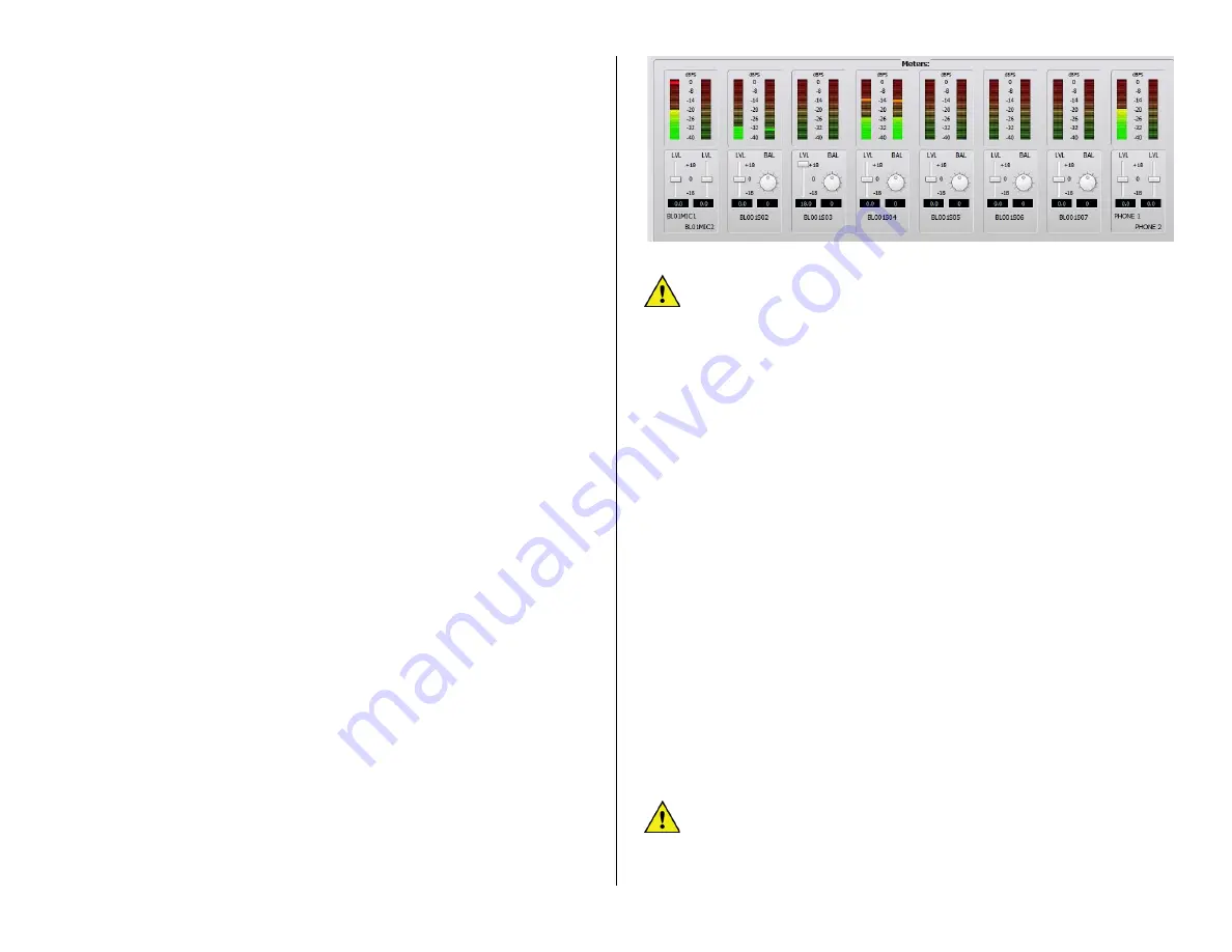
The
Meters
section of the
Sources
and the
Destinations
tab (Figure 3-
29) shows the levels for the stereo and mono inputs, or the stereo and
mono outputs, on the selected Blade (note that a Mix Engine only has
stereo outputs).
Below each meter are level (
LVL
) controls for mono inputs and outputs.
On stereo inputs and outputs there is a level and a round balance (
BAL
)
control. These controls are prior to the meter displays so changing the
level or balance is reflected in the meter display, when audio is present on
that input or output. Since the level control affects the audio in real time,
use caution on live systems when adjusting levels.
Levels are adjusted using any of these methods:
•
Click/drag the level control up (for gain) or down (for trim)
•
Click above/below the level control to add/subtract .5 dB per click
•
Click/hold on the BAL control and drag around the control to pan
the signal left/right
•
Directly enter the amount of gain/trim or balance by highlighting
the level or balance entry number then type in a new number. For
levels, numbers from -18.0 up to +18.0 are valid. For balance,
numbers from -100 (full left) to +100 (full right) are valid. Press
Enter
to assign the new gain or balance entry
Figure 3-29 Meters: Section of the Sources and Destination tabs
Note:
The top of the average signal bar graph should be around
the -20 mark with the peak LED around the -8 mark (to allow for
headroom). On Razor I/O Interfaces, the meters only show
average level bar graphs.
The DMX Surface meters have better resolution than the on-screen
meters so they should be used for the most accurate input level
adjustment. Connect a test tone, at +4 dBu, from a connected device.
Adjust the input control so the top of the bar graph is at -20 dBFS on the
on-screen meters. Assign that signal to a DMX channel. Set the channel
fader to align with the -12 dB unity gain arrows. Turn the channel on and
assign it to a Program bus (with no other channels assigned to that bus).
The D
MX Surface meter’s bar graph should light up all the green LEDs and
one yellow LED, which is the -20 dBFS point on the DMX Surface meters. If
this is not the case, adjust the input level or balance control.
Balanced vs. Unbalanced Inputs & Outputs
One common use for the input level control is to boost the gain of
signals coming from an unbalanced device. Ma
ny “Prosumer” devices use
¼” connectors, but m
ost are unbalanced TS (Tip-Sleeve) instead of
balanced TRS (Tip-Ring-Sleeve) jacks. Their nominal output level is often
the same as that found on
consumer unbalanced “RCA” jacks: 300 mV
instead of the 1.2 V nominal levels found on balanced devices.
The unbalanced dev
ice’s hot signal is connected to the + input and, on a
TS connector, the
–
input will end up being connected to ground. This will
cause the input signal to be 6 dB lower,
since it’s unbalanced, but
it often
has a lower output level to begin with, so typically the level control must
be used to add from +12 dB to +18 dB of gain to compensate for the
lower level from the unbalanced device. Doing this eliminates needing a
level match box on that unbalanced signal.
Note:
A Blade’s balanced output cannot directl
y connect to an
unbalanced device
—
even though the output gain can be lowered to
an appropriate output level, because there is no ground reference
on the Blade’s RJ45 output jacks. Thus,
to properly connect the
Blade to an unbalanced device requires that a balanced-to-
Содержание AUDIOARTS ENGINEERING DMX Series
Страница 1: ...1 Networked AoIP Broadcast Console Manufactured by Wheatstone Corporation ...
Страница 4: ...4 ...


