22
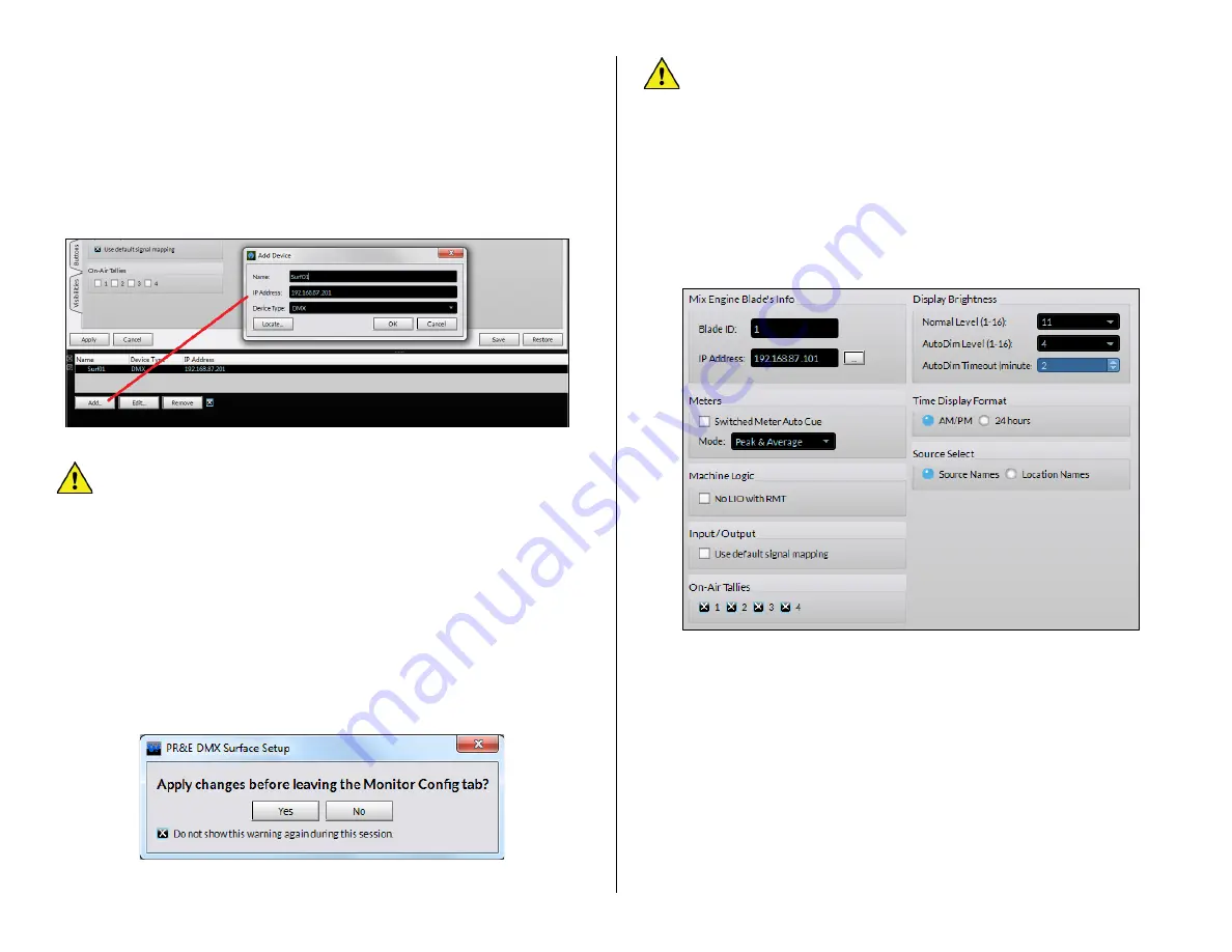
To now connect to that DMX Surface, click on its row to highlight it then
click the small square next to
Remove
(“X” the box). This instructs the
admin PC to contact that Surface.
Surf01 Connected
should appear
momentarily in the lower right corner of the Devices pane which indicates
that DMX Surface is now communicating with the PC. Its current settings
are uploaded to the app to populate the various Page Tabs.
Once the PC is communicating with both the Mix Engine and Surface, the
DMX Surface Setup
app is then used to configure the DMX console for your
specific application.
Figure 3-4 Selecting the DMX Surface in the DMX Setup App
Note:
Several settings, like editing the
console’s
default signal
names, editing their signal formats, and configuring logic, are done
using
Navigator
. Information on using it starts on page 31).
Device Properties Page Tabs
The DMX Surface Setup page tabs are divided into sections to group
similar configuration settings. Changes made on a page tab are all
“pending” until
the
Apply
button, just below the page tabs, is clicked to
upload the changes to the DMX Surface.
If you’ve made changes on a page
tab but did not click
Apply
before
clicking on another page tab, you
’ll
get a pop-up warning (Figure 3-5)
about applying changes to the previous page tab. Clicking
Yes
applies the
changes. Clicking
No
discards all changes made on the previous tab since
the last time
Apply
was clicked.
Figure 3-5 Apply Changes Warning Pop-Up
Note:
We recommend
unchecking
Do not show this warning
again during this session
before clicking Yes or No so that you
keep getting the popup. If left checked the popup no longer
appears but the default selection is
No
which means if you switch
to a new page tab any unapplied changes on the previous page tab
will be discarded.
Engine Page Tab
The
Engine
page tab has eight sections: Mix Engine Bla
de’s Info
(covered in
Setting the Surface Host
section on page 21), Meters, Machine
Logic, Input/Output, On-Air Tallies, Display Brightness, Time Display
Format, and Source Select which affect the overall Surface operation.
Figure 3-6 Engine Page Tab
Meters
When
Switched Meter Auto Cue
is checked (click the box to add an X)
the cue bus level is shown in the switched meter when cue is active. This
overrides the source set by the Meter Select buttons. When unchecked,
the default setting, cue does not affect the switched meter display.
The
Mode:
setting affects all three meters.
Peak and Average
is the
default setting, but the meters can alternately show
Average Only
or
Peak
only
for special applications. The Average signal level is shown using a bar
graph display while the Peak level is shown using one LED per channel, to
indicate the highest instantaneous audio level, which is typically 6
–
12 dB
above the top of the average level bar graph. Note that the Peak decay
time is fixed.
Содержание AUDIOARTS ENGINEERING DMX Series
Страница 1: ...1 Networked AoIP Broadcast Console Manufactured by Wheatstone Corporation ...
Страница 4: ...4 ...


