


page 11 – 3
D500 / Jul 98
I N T E R C O M M O D U L E
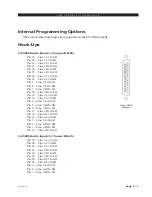
Internal Programming Options
All internal programming, except for address selections (see below), is
made via printed circuit board (PCB) mounted 4-position dipswitches (total
two) on the module’s main card.
For the purposes of this manual, we will assume you are holding the removed
module upright, component side towards you, with gold-plated card fingers to the
left and the module faceplate to the right. This will enable you to read the control
legends silkscreened next to the programming switch. Note when a dipswitch
position is thrown to the right (towards the module’s faceplate) it is ON.
CUE Enable
You can program the ICMD-500 module (via dipswitch SW10) to
perform a cue interrupt function. The caller’s voice will appear at the control
room speakers and/or operator headphones, depending on how you have
programmed your CRD-500 module to handle CUE.
Dipswitch SW10 position 1 assign CUE Logic Enable
Input Signal
Your microphone signal can tap from the console’s talkback bus, where
it picks up the regular console operator’s microphone, or it can be a separate
line level input coming into the ICMD-500 module.
Dipswitch SW 1 position 1 assign line level input into ICMD module
Dipswitch SW 1 position 4 allows microphone signal tap from the
console’s talkback bus
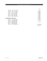
Power for Various ICMs
Your can provide power for other Wheatstone rackmount ICM (via
dipswitch SW10)
position 2 - Ext +V
position 3 - Ext -V
position 4 - Ext +D
Station Select
Each ICM in daisy-chain hookup has own address, which is programed
with “stations” slide switches SW2-SW9. Each ICM has only one slide
switch “ON”.
A-5000 / Nov 98