


page 8 – 6
A-5000 / Nov 98
S U P E R P H O N E I N P U T
Programming Options
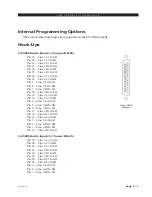
The module’s logic control programming is accomplished via four 4-
position printed circuit board (PCB) mounted dipswitches mounted just to the
left of the module’s faders.
For main PCB programming, we will assume you are holding the removed
module upright, component side towards you, with gold-plated card fingers to the
left and the module faceplate to the right. This will enable you to read the control
legends silkscreened next to each dipswitch. Note when a dipswitch position is
thrown to the right (towards the module’s faceplate) it is ON.
Dipswitch SW1 Functions
Mutes
When the SPN-5000 phone channel ON/START switch is pressed, it can
activate console mute functions. The first three positions of dipswitch SW1
determines which of the console’s three mute lines will be activated:
SW1 position 1 mutes the control room when the phone module is ON*
SW1 position 2 mutes studio one when the phone module is ON
SW1 position 3 mutes studio two when the phone module is ON
Timer Restart
The console’s digital timer can be programmed to automatically reset to
zero and begin counting up when the module’s ON button is pressed.
SW1 position 4 activates timer restart when the phone module’s ON/
START switch is pressed*
Dipswitch SW2 Functions
Feed Follow Selectors
When SPN-5000 is Turned ON
SW2 position 1 - Callers will hear the EXTERNAL INPUT
SW2 position 2 - Callers will hear the MXM1 feed
SW2 position 3 - Callers will hear the MXM2 feed
Drop Cue1
SW2 position 4 - The DROP1 switch will also drop Caller 1 from CUE
with this dipswitch active.
Dipswitch SW3 Functions
Feed Follow Selectors
When SPN-5000 is Turned OFF
SW3 position 1 - Callers will hear the EXTERNAL INPUT
SW3 position 2 - Callers will hear the MXM1 feed
SW3 position 3 - Callers will hear the MXM2 feed
*factory default setting
*factory default setting