


page 8 – 4
A-5000 / Nov 98
S U P E R P H O N E I N P U T
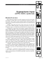
Factory default setting for
these trimpots is UNITY
GAIN.
Cue Audio
The module’s CALLER CUE switches (ANSWER CUE/TB buttons 1 &
2) assign pre-fader CALLER 1(2) audio to the cue bus. This switch also picks
up the pre-fader DJ mic channel assigned to the TB bus and routes it to caller.
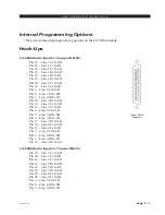
Gain Trimpots
There are seven PCB-mounted trimpots. They are used as follows:
CR1 – sets the Caller 1 In port input gain
CR2 – sets the Caller 2 In port input gain
CR7 – sets the module’s output level to Hybrid 1
CR3 – sets the module’s output level to Hybrid 2
CR5 – sets the module’s “composite” output level
CR6 – sets the module’s “composite minus callers” (“talent”)
output level (labeled FEED on PC card)
CR4 – sets the module’s “callers only” output level
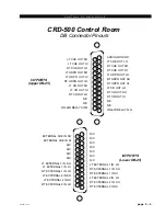
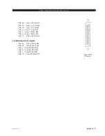
Phone System Control
The SPN-5000 includes four opto-isolated phone system control outputs
that may be used to simplify answering and dumping callers. These control
signal outputs are located on the module’s LOWER DB-25 connector and are
labeled ANSWER CALLER 1, ANSWER CALLER 2, DROP CALLER 1 and
DROP CALLER 2.
Answer Caller Outputs
Whenever the CUE CALLER 1 switch is pressed on the SPN-5000, a
corresponding opto-isolated, momentary closure is made across LDB pins 2
and 4 (for CUE CALLER 2, LDB Pins 3 and 4). These logic signals can be
connected to your hybrid’s ANSWER control input. Be sure to observe polarity
when making these connections. ANSWER COM, LDB Pin 4, is the reference
or negative side.
Drop Caller Outputs
Whenever the DROP CALLER 1 switch is pressed on the SPN-5000, a
corresponding opto-isolated momentary closure is made across LDB Pins 15
and 17 (for DROP CALLER 2, LDB Pins 16 and 17). These logic signals can
be connected to your hybrids DROP CALLER (i.e. hang up) control inputs. Be
sure to observe polarity when making these connections. DROP COM, LDB
Pin 17 is the reference or negative side.
front panel
trimmers
internal
trimmers