10
Westward Operating Instructions and Parts Manual 1KEN3, 1KEN4
10”,12” Drill Presses
Adjustments instructions
NOTE:
All the adjustments for the operation of the drill press
have been completed at the factory. Due to normal wear and
use, some occasional readjustments may be necessary.
WARNING
!
To avoid injury from an accidental
start, ALWAYS make sure the switch is in the “OFF”
position, the switch key is removed, and the plug is not
connected to the power source outlet before making belt
adjustments.
Squaring table to head (Figure. 15, 16)
NOTE:
The table arm and support has a predrilled hole
with a locking set screw inserted for locking the table to a
predetermined 0° horizontal position. It must be loosened to
change the angle of the table.
1. Insert a 1/4”, or larger diameter, precision ground steel rod
(1), approximately 3” long, into the chuck (2). Tighten the
chuck jaws.
2. Raise table to working height and lock.
3. Using the combination square (3), place one edge fl at on
the table, and align the other edge vertically beside the rod
(1).
4. (Figure 16) If an adjustment is necessary, loosen the
locking set screw (4) with the 3 mm hex key to RELEASE
the table from the horizontal position.
5. Loosen the large hex head bevel locking bolt (5).
WARNING
!
To prevent injury, be sure to hold
the table and table arm assembly, so it will not swivel or
tilt.
6. Align the square to the rod by rotating the table until the
square and rod are in line.
7. Retighten the large hex bolt (5).
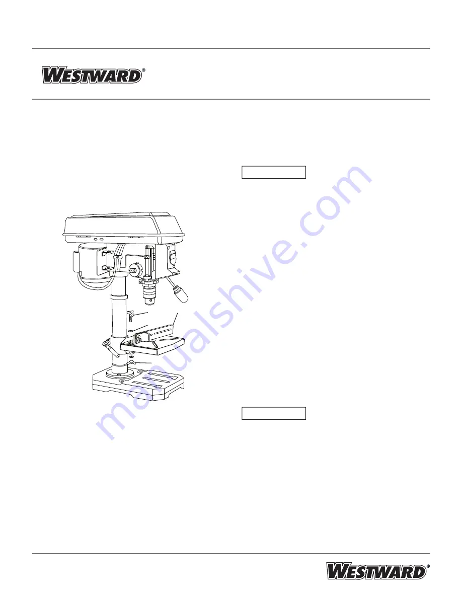
Fence assembly (Figure 14) - (The fence assembly has
been supplied for 12” drill press only.)
1. Align the mounting holes of the fence over the table slots.
2. Place a washer (2) on the threaded end of the knob (3).
Insert the knob through the mounting hole of the fence and
the table slot.
3. Place a washer and wing nut (4) on the knob from under
the table.
4. Repeat for the other knob and tighten.
Figure 14
1
3
2
4


