14
Westward Operating Instructions and Parts Manual 1KEN3, 1KEN4
10”,12” Drill Presses
Operation
Basic drill press operation
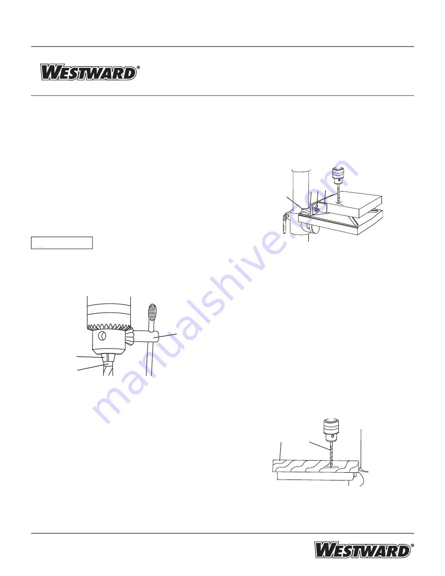
Installing drill bit in chuck (Figure 23)
1. With the switch “OFF” and the switch key removed,
open the chuck jaws (1) using the chuck key (2).
Turn the chuck key counterclockwise to open the
chuck jaws (1).
2. Insert the drill bit (3) into the chuck far enough to
obtain maximum gripping by the jaws, but not far
enough to touch the spiral grooves (fl utes) of the drill
bit when the jaws are tightened.
3. Make sure that the drill is centered in the chuck.
4. Turn the chuck key clockwise to tighten the jaws.
To avoid injury or accident by the
chuck key ejecting forcibly from the chuck when the
power is turned “ON”, use only the self-ejecting chuck
key supplied with this drill press. ALWAYS recheck and
remove the chuck key before turning the power “ON”.
Figure 23
Using the fence (Figure 24) (The fence assembly has been
supplied for 12” drill press only.)
The fence provides a way of accurately and quickly
setting up the workpiece for precision or for repitive
drilling operations.
1. Using a centerpunch or sharp nail, make an
indentation in the workpiece where you want to drill.
2. Align the laser lines (x) with the indentation on the
workpiece.
3. Loosen the knobs (1) and slide the fence back stop (2)
fi rmly against the long side of the workpiece. Tighten the
knobs when in position.
4. Loosen the wing nut (3) and slide the end stop (4)
along the fence until it is fi rmly against the left side of the
workpiece. Tighten the wing nut.
5. Check the accuracy by drilling into a scrap workpiece
fi rst. Adjust if needed.
6. Hold with your hand or clamp the top surface of the
workpiece fi rmly to prevent it from lifting off the table when
the bit is raised.
Figure 24
Drilling to a specifi c depth
Drilling a blind hole (not all the way through workpiece) to a
given depth can be done two ways:
Workpiece method (Figure 25 and Figure 26)
1. Mark the depth (1) of the hole on the side of the workpiece
(Figure 25 ).
2. With the switch “OFF”, bring the drill bit (2) down until the
tip is even with the mark (Figure 25).
3. Hold the feed handle at this position.
4. Spin the lower nut (3) down to contact the depth stop lug
(6) on the head (Figure 26).
5. Spin the upper nut (5) down and tighten against the lower
nut (3) (Figure 26).
6. The drill bit will now stop after traveling the distance
marked on the workpiece.
Figure 25
WARNING
!
1
3
2
1
2 33 44
2
1


