• Through Dovetail
• Lapped/Half Blind Dovetail
• Finger/ Box Joint
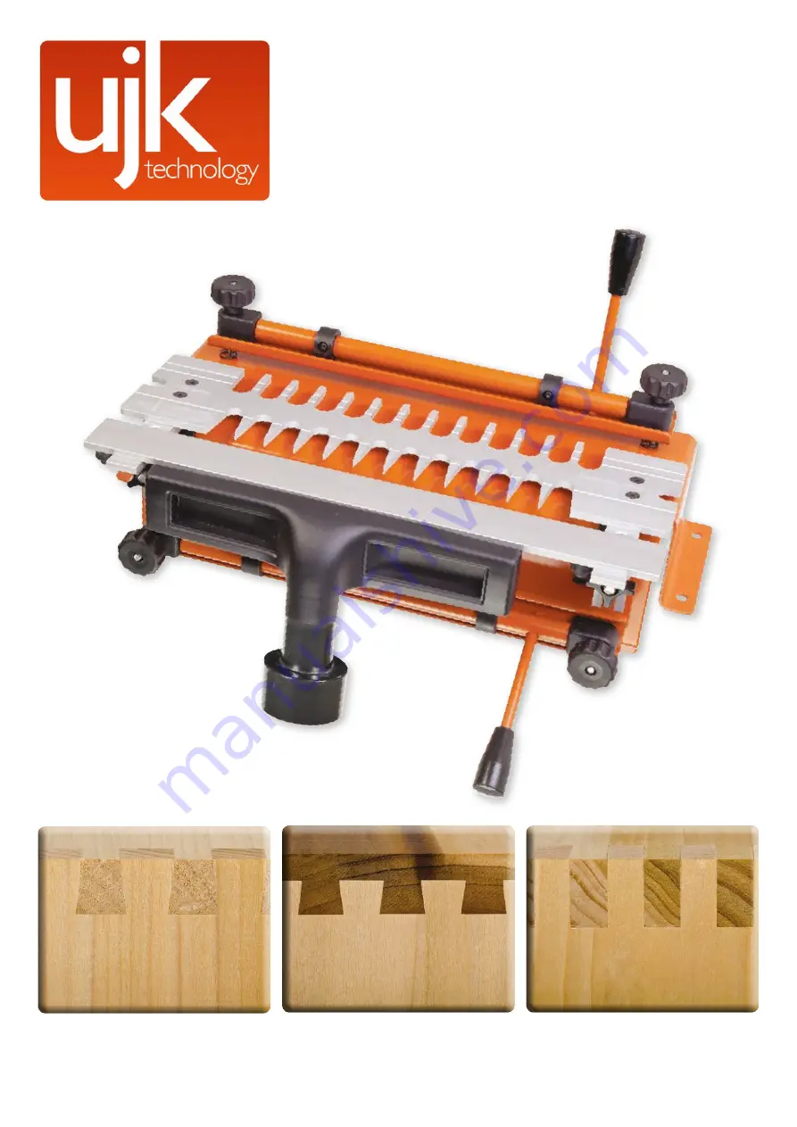
Dovetail Jig
Code 506300
Original Instructions
AT&M: 29/05/2019
BOOK REF : 508484
Страница 1: ...Through Dovetail Lapped Half Blind Dovetail Finger Box Joint Dovetail Jig Code 506300 Original Instructions AT M 29 05 2019 BOOK REF 508484...
Страница 2: ...s Description 08 09 10 Dovetail Jig Set up 11 UJK Dovetail Jig Processes Chapter 0 1 Process forThrough Dovetail 12 13 14 15 16 17 Chapter 0 2 Process for Lapped Half Blind Dovetail 17 18 19 20 21 22...
Страница 3: ...ovetail Guide D 1 No Through Dovetail and Finger Joint Guide E 1 No Dust Extraction Moulding F 1 No 63mm Adaptor G 2 No Guide Bushes H 1 No Butterfly Hex Key I Bags Comprising 4 No Countersunk Hex Scr...
Страница 4: ...2 x 6mm thick aluminium guide templates The following will enable you to observe good working practices keep yourself and fellow workers safe and maintain your tools and equipment in good working ord...
Страница 5: ...ted securely If dust extraction is available connect it 3 Check that all accessories tools etc that have been used to set the machine up are removed and set carefully aside or stowed away correctly 4...
Страница 6: ...ine up the elongated slots in the support brackets B with the threaded studs to either side of the jig and lower the assembly down until the dovetail guide is seated down on top of the jig Tighten the...
Страница 7: ...the comb bar supports B and insert the rails to the under of the mounting plate C into the machined slots in the comb bar supports Lock the stops K against the support brackets B see fig 11 12 Fig 09...
Страница 8: ...d Parts Description 8 Horizontal Clamp bar handle Horizontal cam bar Clamp bar Dovetail mounting bracket Pressure adjustment knob Router cutter depth stop Vertical cam bar Extraction outlet Pressure a...
Страница 9: ...9 Vertical cam clamps A and clamp bar B Horizontal cam clamps A and clamp bar B Router cutter depth adjuster Pin Depth Outer clamping star knob A Inner brass depth wheel B Guide bush Dovetail joint gu...
Страница 10: ...on 10 Mounting bracket holes Vertical pressure adjustment knob Side stop cap screw A Side stop B Horizontal clamping bar assembly Clamping bar plate Support plate for extraction outlet Dovetail jig re...
Страница 11: ...then be stored away when not in use Fig A Preparation of Timber As with all joinery work the drawer or box components must be sized and cut square and accurately It is preferable that the width of the...
Страница 12: ...a depth line across the end of the boards use the boards to set the cutting gauge up take one jointing corner set the gauge to the thickness of one board see fig 03 Once the gauge is set mark this de...
Страница 13: ...ccentric cam bar handle downwards see fig 08 0 1 Fig 08 Equal distance 0 1 Fig 09 9 Undo the hex cap screw that holds the side stop in place slide the side stop over to reposition this up against the...
Страница 14: ...router still unplugged carefully position the router on the jig Locate the guide bush within the fingers of the comb then adjust the cutter height so that the tip of the cutter is level with the scri...
Страница 15: ...sed for setting up the cutter height for cutting the Pin board To use this place the Tail board in the horizontal position in the jig and lock in place with the eccentric bar clamp Adjust the height o...
Страница 16: ...the jig and check that the tip of the straight cutter meets the scribe line as cut with the cutting gauge see fig 26 0 1 Fig 26 Scribe line 21 On the face of the template is one preset line that runs...
Страница 17: ...s adjustment wheel clockwise see fig 34 how much will depend on how tight the joint is and the type of wood being jointed together This needs to be done evenly on both side of the jig to keep the comb...
Страница 18: ...outer base with flange step facing down see fig 38 39 40 41 Ensure that power is disconnected Guide bush adaptor Cutter shank Collet Visual mark Flange facing down Dovetail cutter 3 4 guide bush Fixin...
Страница 19: ...g surface test with a finger tip and adjust boards as needed it is important to get the joint point of these two boards level see fig 44 6 Having lined up the boards it is important to centralise the...
Страница 20: ...in the project as the joint fit will also need to be adjusted due to material density see fig 51 0 2 Fig 51 11mm 11 Replace the extraction support bar and connect the hose to vacuum extractor 12 Chec...
Страница 21: ...n the jig having been cut in the offset position see fig 54 55 0 2 Fig 54 55 18 Remove the two boards from the jig and assemble them 19 Check how the two boards fit together it is now possible to adju...
Страница 22: ...Fig 57 Draw front Draw side To get this level undo the black star locking knobs and turn the brass adjustment knobs anti clockwise to move the comb towards the user re lock the comb in place The same...
Страница 23: ...maging the jig or cutter To do this loosen both the black locking knobs that fix the comb bar brackets to the jig and lift the comb bar up Insert a board to support the raised comb bar this board need...
Страница 24: ...int carefully position the router out of the way and inspect the joint The cutter should have passed all the way through the workpiece the edges of the cut should be straight and free of any lumps or...
Страница 25: ...rew 14 Position the other board within the vertical position of the jig ensure that this lies parallel to the side stop and also meets squarely on the underside of the comb bar Remember that the comb...
Страница 26: ...Exploded Diagram Parts List 26...
Страница 27: ...17 A206014012031D RND HD SCREW 2 18 DJA1 10B LEFT OFFSET GUIDE 1 19 DJA1 1 STABILIZER BAR 1 20 D235014000011Z SLIDING NUT 4 21 DJA1 17 LOCK KNOB 2 22 E0811060033D SPRING WASHER 2 23 A211014038031D SCR...
Страница 28: ...into the appropriate recycling bin The UJK technology brand was launched by Axminster in 2012 with the intention of encompassing a range of carefully selected products that Axminster held in particula...