User Guide
3. Support
3.9 Chassis Replacement
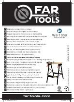
Figure 178:
Removing IOM
Step 17 :
Remove the second IOM.
Step 18 :
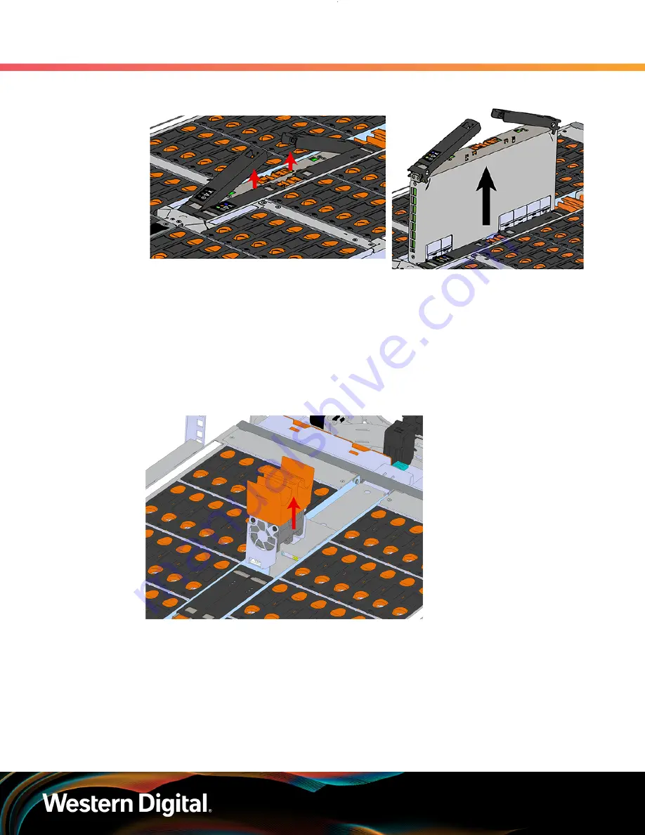
Remove the IOM Fan.
a.
With one hand, grasp around the center square of the fan housing as shown in the following
image.
b.
Pinch the IOM fan housing to release the latching mechanism and pull it straight out from the
chassis.
Figure 179:
Removing IOM Fan
Step 19 :
Release the safety latch on the inner rails on each side of the chassis as shown in the following
image.
154
Содержание 1EX1231
Страница 1: ...User Guide Ultrastar Data102 Regulatory Model H4102 J Document D018 000226 000 Revision 04 May 2022...
Страница 16: ...User Guide Points of Contact xv...
Страница 110: ...User Guide 3 Support 3 7 CMA Replacement Figure 91 CMA Cable Routing c Open all of the baskets Figure 92 Open Baskets 94...