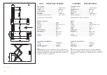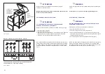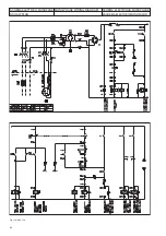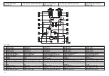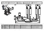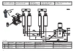
Fig.8 - Abb.8
CAP. 4
INSTALLAZIONE
I
ATTENZIONE
TUTTE QUESTE OPERAZIONI DEVONO ESSERE
ESEGUITE DA PERSONALE ESPERTO E AUTORIZZATO.
SEGUIRE ATTENTAMENTE LE INDICAZIONI SOTTO
RIPORTATE AL FINE DI EVITARE DANNI ALLE
PERSONE E AL SOLLEVATORE STESSO.
ASSICURARSI CHE NELLA ZONA DI RISCHIO NON CI
SIANO PERSONE, NEL CASO ALLONTANARLE.
L’ installazione del ponte sollevatore è di competenza dei tecnici spe-
cializzati, incaricati dal costruttore o dai rivenditori autorizzati.
La non osservanza di questa norma può causare seri danni alle perso-
ne e alle cose.
REQUISITI PER L’ INSTALLAZIONE (fig. 8)
Il sollevatore deve essere installato rispettando le distanze di sicurezza
da muri, colonne, altre macchine etc.
La distanza minima dai muri, considerando lo spazio per lavorare co-
modamente deve essere almeno di 1000 mm. Bisogna poi considerare
gli spazi per la postazione di comando, per le vie di fuga in caso di
emergenza. Il locale deve essere preventivamente predisposto per l’
alimentazione elettrica del ponte. L’ altezza del locale deve essere mi-
nimo di 5000 mm.
Il sollevatore può essere piazzato su qualsiasi tipo di pavimento, purchè
lo stesso sia perfettamente piano, orizzontale, nonchè di resistenza
adeguata ( min. 250 Kg. x cm
2
.).
La centralina può essere posizionata sia sul lato destro che
sinistro del sollevatore (vedere collegamenti idraulici fig.15-16).
SEQUENZA DELLE OPERAZIONI PER LA MESSA IN FUNZIONE
DEL SOLLEVATORE
1 -Posizionamento delle pedane
2 -Collegamenti idraulici ed elettrici
3 -Riempimento impianto idraulico
4 -Livellamento pedane
5 -Fissaggio pedane
6 -Controllo finale:
-funzionamento rampe salita
-allineamento pedane
-micro alto (la salita deve arrestarsi prima della fase di travaso)
-micro antiribaltamento (interponendo un ostacolo,sotto alle piattaforme il
sollevatore deve arrestarsi) e micro salvapiedi (il sollevatore deve
arrestarsi a 45cm dal pavimento durante la discesa)
- A 45 cm dal suolo il sollevatore si arresta, per compiere la discesa
completa rilasciare e ripremere il pulsante "discesa"
CHAPTER 4
INSTALLATION
I
WARNING
SKILLED AND AUTHORIZED PERSONNEL ONLY
SHOULD BE ALLOWED TO PERFORM THESE OPE-
RATIONS.
FOLLOW ALL INSTRUCTIONS SHOWN BELOW CA-
REFULLY, IN ORDER TO PREVENT POSSIBLE DA-
MAGE TO THE CAR LIFT OR RISK OF INJURY TO
PEOPLE. BE SURE THAT THE OPERATING AREA IS
CLEARED OF PEOPLE.
Skilled technicians only, appointed by the same manufacturer or by aut-
horized dealers, are allowed to install the car lift. Serious damage to
people and equipment can be caused if this rule is not followed.
INSTALLATION REQUIREMENTS (fig.8)
The car lift must be installed according to the specified safety distances
from walls, columns, other equipments, etc. The minimum distance
from walls must be 1000 mm at least, taking into consideration the ne-
cessary space to work easily. Further space for the control site and for
possible runways in case of emergency is also necessary. The room
must be previously arranged for the power supply eed of the car lift.
The room must be 5000 mm in height, at least. The car lift can be pla-
ced on any floor, as long as it is perfectly levelled and sufficiently resi-
stant (250 Kg X sq.cm. Min).
The power package can be placed on the right side or on the left
side of the car lift (see hydraulic diagram fig.15-26)
SUCCESSION OF THE OPERATIONS NECESSARY TO PUT THE
LIFT IN WORKING CONDITIONS
1 -Platform arrangement.
2 -Hydraulic and electric connections
3 -Hydraulic circuit filling
4 -Platform levelling
5 -Platform fixing
6 -Final check:
-on-ramps operation
-platform alignment
-high position microswitch (lifting must stop before the oil transfer phase)
- Anti-tilting micro-switch (putting an obstacle under the platforms the
lift stops) and foot guard micro-switch (the lift stops 45cm over the
floor during the descent).
- At a height of 45 cm from ground the lift will automatically stop. In or-
der to carry out the remaining descent stroke, release the descent but-
ton and press it again until the lift has reached its ‘zero’ position
18
Direzione veicoli
Vehicles direction
Sens d’accès
Auffahrrichtung
Dirección vehículos
Содержание STRATOS SRM
Страница 2: ......
Страница 49: ......
Страница 51: ...QUADRO DI COMANDO CONTROL BOX STEUERTAFEL TABLEAU DE COMMANDE PANEL DE MANDO...
Страница 52: ...CENTRALINA OLEODINAMICA OLEODYNAMIC CONTROL UNIT HYDRAULIKEINHEIT CENTRALE HYDRAULIQUE CENTRALITA HIDRAULICA...
Страница 57: ......


