075 (Part)
55
Wire
Starts at:
Ends at:
Use, Remarks
No.
(Subunit, PC board, terminal)
(Subunit, PC board, terminal)
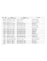
391 On ye/bn Right control paneI,SW6,point PK
Left control panel, SW 3, point 7
Manual coupler override
392 W, bn
Right control panel, SW 6, point 29
Arpeggio, AG 1, plug 2, pin 1
Arpeggio Inversion
393 W, ye
Right control panel, SW 6, point 30
Arpeggio, AG 1, plug 2, pin 17
Arpeggio Chords
394 , On gy
Right control panel, SW 6, point 31
Arpeggio, AG 1, plug 2, pin 16
Memory off
395 W, w
Right control panel, SW 6, point 32
Arpeggio, AG 1, plug 2, pin 18
U/M Piano off
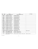
396 W, pk
i Right control panel, SW 6, point 21 I
Arpeggio, AG 1, plug 1, pin 6
Arpeggio
397 On r/bl
Right control panel, SW 6, point 22
Arpeggio, AG 1, plug 1, pin 5
Arpeggio
398 W, ye/bn Right control panel, SW 6, point 23
Arpeggio, AG 1, plug 1, pin 8
Arpeggio
399 W, w/r
Right control panel, SW 6, point 24
Arpeggio, A G 1, plug 1, pin 7
Arpeggio
400 W, w/bn Right control panei,SW 6, point 13
Arpeggio, AG 1, plug 2, pin 13
Auto Trigger
401 W,ye/r
Right control panel. SW 6, point 14
Arpeggio, AG t, plug 2, pin 14
Foot Trigger Off
402 W, ye/bk
Right controlpanel,"Arpeggio Speed",
term. e
Arpeggio, AG 1, plug 1, pin 15
Arpeggio Speed
403 W, ye/bk
Right control panel," Arpeggio Speed",
terms
Arpeggio, AG 1, plug 1, pin 9
Arpeggio Speed
404 W, gy
Arpeggio control, term S
Arpeggio, AG 1, plug 1, pin 2
Slide control
405 W, w/bl
Arpeggio control, term. A
Arpeggio, AG 1, plug 1, pin 3
Slide control
406 W, w/bk Arpeggio controkterrn. F
Arpeggio, AG 1, plug 1, pin 4
Slide control
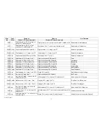
407 W,ye/r
Aux. power supply, PS 5, plug 3, pin 1 L/M sound comp., SCI plug 2, pin 22
- 3 3 V D C
408 W, ye/r
Aux. power supply, PS 5, plug 3, pin 2 M/M sound comp., SC 5, plug 2, pin 22
- 33 V D C
409 W, ye/r
AUX, Dowersupply,PS5,plug3,pin 3
U/M sound comp., SC 5,plug2,pin 22I
-33 V DC
410 W, gy j
"Read-in" key switch
Left control panel, SW 3, point 8
"Read-in" Inhibit
411 On gy I
"Read in- key switch
L/M sound comp., SC 3, plug 1, pin 11
"Read-in" Inhibit
412 W,gy
"Read-in" key switch
M/M sound comp., SC 5, plug 1, pin 11
"Read-in" Inhibit
413 W, gy
"Read-in" key switch
U/M sound comp., SC 5, plug 1, pin 11
"Read-in" Inhibit
414 W, w
Left control panel, SW 3, point 1
L/M sound comp., SC 3, plug 1, pin 12
L/M Clock Trigger
415 AW, ye
Left control panel, SW 3, point 2
M/M sound comp., SC 5, plug 1, pin 12
M/M Clock Trigger
416 W,bn
Left control panel, SW 3,point3
LI/M sound comp., SC 5, plug 1, pin 12
U/M Clock Trigger
Type/
Color
AM
Содержание GALAXY
Страница 1: ...Master Assembly GALAXY AM 075 AM 075 Part 1 ...
Страница 4: ...Figure 1 Layout of the building blocks in the organ top AM 075 Part 4 ...
Страница 5: ...Figure 2 Block diagram of the audio distribution and associated DC controls AM 075 Part 5 ...
Страница 6: ...AM 075 Part 6 ...
Страница 33: ...Figure 4 Schematic layout of the wiring harness GO 4 AM 075 Part 33 ...


