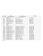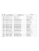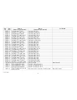
The wiring list on the following pages contains the wire numbers, colors and types of wires used in the harness GO 4. Beginning and end of each wire are also identified
as to subunit name and terminal designation as far as the wiring of the organ is concerned, we do not make use of this list. It is provided as an aid in trouble-shooting and
for future reference.
Table 2 Wire List of Harness GO 4
Wire
Type/
Starts at:
Ends at:
Use, Remarks
No.
Color
(Subunit, PC board, terminal)
(Subunit, PC board, terminal)
1 W, r
Power supply, PS 4,+15 V
L/M fixed stops, G P 1, plug 2, pin +15
Pos.supply voltage
2 W, r
Power supply, PS 4, +15 V
M/M fixed stops, G P 1, plug 2, pin +15
Pos. supply voltage
3 W, r
Power supply, PS 4, +15 V
U/M I fixed stops, G P 1, plug 2, pin +15
Pos.supply voltage
4 W, r
Power supply, PS 4, +15 V
U/M Ilfixed stops, DS 1, plug t, pin 2
Pos.supply voltage
5 W, r
Power supply, PS 4, +15 V
Swell indicator, LA 1, plug 1, pin +15
Pos.supply voltage
6 W, r
Power supply, PS 4, +15 V
D B presets, PZ 6, plug 1, pin 15 V+
Pos.supply voltage
7 W, r
Power supply, PS 4, +15 V
L/M presets, PZ 4, plug 1, pin 15 V+
Pos.supply voltage
8 W, r
Power supply, PS 4, +15 V
M /M presets, PZ 4, plug 1, pin 15 V+
Pos.supply voltage
9 W, r
Power supply, PS 4, +15 V
U/M presets, PZ 4, plug 1, pin 15 V+
Pos.supply voltage
10 W, r
Power supply, PS 4, +15 V
Key pop, H P 1, pin +V
Pos.supply voltage
11 W, r
Power supply, PS 4, +15 V
Wersivoice 11, W V 7, pin 11
Pos.supply voltage
12 W, r
Power supply, PS 4, +15 V
Wersivoice I, WV 7, pin 11
Pos.supply voltage
13 W, r
Power supply, PS 4, +15 V
U/M spec. eff., E F 1, pin 19
Pos.supply voltage
14 W, r
Power supply, PS 4, +15 V
M /M spec. eff., E F 1, pin 19
Pos.supply voltage
15 W, r
Power supply, PS 4, +15 V
Left studio amp, SV 7, pin +15 V
Pos. supply voltage
16 W, r
Power supply, PS 4, +15 V
Right studio amp, SV 7, pin +15 V
Pos.supply voltage
17 W, r
Power supply, PS 4, +15 V
Board CO 4, point 35
Pos.supply voltage
18 W, r
Power supply,PS 4,+15 V
Generator 11,G t, plug A, pin 4
Pos.supply voltage
19 W, r
Power supply, PS 4, +15 V
Generator I, G 1, plug A, pin 4
Pos.supply voltage
20 W, r
Power supply, PS 4, +15 V
Piano, PI 1, plug 3, pin +15
Pos.supply voltage
21 W, r
Power supply,PS 4,+15 V
L/M Keyers,V 3, pin +15
Pos.supply voltage
22 W, r
Power supply, PS 4,+15V
M/M Keyers,V 3, pin +15
Pos.supply voltage
23 W, r
Power supply,PS4,+15V
U /M Keyers,V 3, pin +15
Pos.supply voltage
24 W, r
Power supply, PS 4, +15 V
Right preamp, VV 2, plug 5, pin +15
Pos.supply voltage
AM 075 (Part)
34
Содержание GALAXY
Страница 1: ...Master Assembly GALAXY AM 075 AM 075 Part 1 ...
Страница 4: ...Figure 1 Layout of the building blocks in the organ top AM 075 Part 4 ...
Страница 5: ...Figure 2 Block diagram of the audio distribution and associated DC controls AM 075 Part 5 ...
Страница 6: ...AM 075 Part 6 ...
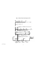
Страница 33: ...Figure 4 Schematic layout of the wiring harness GO 4 AM 075 Part 33 ...

