Wire
Starts at:
Ends at:
Use, Remarks
No.
(Subunit, PC board, terminal)
(Subunit, PC board, terminal)
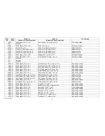
276a W,bn
Transposerswitch, TP,pointc
Twin transp.1,plug 2,pin c
276b W, bn
Twin transp.l, TP 2, plug 2, pin c
Twin transp.11, plug 2, pin c
277a W,ye
Transposerswitch, TP,pointc #
Twin transp.1,plug 2, pin cis
277b W, ye
Twin transp.l, TP 2, plug 2, pin cis
Twin transp.ll, plug 2, pin cis
278a W,gy
Transposes switch, TP, point d
Twin transp.1, plug 2, pin d
278b W,gy
Twin transp.l, TP 2, plug 2, pin d
Twin transp.ll, plug 2, pin d
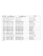
279a W, w
Transposer switch, TP, point d #
Twin transp.1, plug 2, pin dis
279b W, w
Twin transp.l, TP 2, plug 2, pin dis
Twin transp.11, plug 2, pin dis
280a W, pk
Transposer switch, TP, point a
Twin transp.l, plug 2, pin a
280b W, pk
Twin transp.l, TP 2, plug 2, pin a
Twin transp.ll, plug 2,pin a
281a I W,r/bl
Transposer switch, TP, point f
Twin transp.l, plug 2, pin f
281b VV, r/bl
Twin transp.l, TP 2, plug 2, pin f
Twin transp.ll, plug 2, pin f
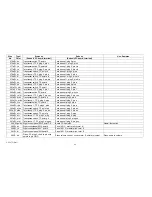
282a W,ye/bl Transposerswitch, TP,point b
Twin transp.l,plug 2, pin ces
282b W, ye/bl Twin transp.l, TP 2, plug 2, pin ces
Twin transp.ll, plug 2, pin ces
283a W, w/bk Transposerswitch, TP,point b b
Twin transp.l,plug 2,pin b
283b i W, w/bk Twin transp.1, TP 2, plug 2, pin b
Twin transp.ll, plug 2, pin b
284a W,r/ye
Transposerswitch, TP,point a I
Twin transp.l,plug 2,pin a
284b W, r/ye
Twin transp. I, TP 2, plug 2, pin a
Twin transp.ll, plug 2, pin a
285a W, w/bn Transposes switch, TP, point a b
Twin transp.l, plug 2, pin as
285b, W w/bn Twin transp.l, TP 2, plug 2, pin as
Twin transp.ll, plug 2, pin as
286a W, w/r I Transposes switch; TP, point g
Twin transp.l, plug 2, ping
286b W, w/r
Twin transp.l, T P 2, plug 2, ping
Twin transp.ll, plug 2, ping
287a W, w/bl
Transposes switch, TP,point g b
Twin transp.l,plug 2, pin ges
287b W, w/bl
Twin transp.l, T P 2, plug 2, pin ges
Twin transp.ll, plug 2, pin ges
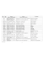
288 W,gn/bk Right control paneI,SW 5, point FS
Board CO 4,point34
Hawaii foot switch
289 W,bk
Right controlpanel,SW 6,point A
Panel AP 1G, master pitch,term. A
290 W,ye
Right controlpanel,SW " point S
Panel AP 1 G, master pitch, term. S
291 W, b!
Right control paneI,SW6,point E
Panel AP 1 G, master pitch, term. E
292 S, bn
Piano, P!1, plug 3, cond to pin nutp
,shield to pin G N D
Piano volume control, cond.to term. E, shield to jumper
Piano audio to volume
Type/
Color
AM 075 (Part)
49
Содержание GALAXY
Страница 1: ...Master Assembly GALAXY AM 075 AM 075 Part 1 ...
Страница 4: ...Figure 1 Layout of the building blocks in the organ top AM 075 Part 4 ...
Страница 5: ...Figure 2 Block diagram of the audio distribution and associated DC controls AM 075 Part 5 ...
Страница 6: ...AM 075 Part 6 ...
Страница 33: ...Figure 4 Schematic layout of the wiring harness GO 4 AM 075 Part 33 ...


