daughter board V V 1 is not working properly). The V V 1 boards
are interchangeable as long as the reverb is not hooked up.
If the tones from. the drawbar inputs are audible but not from the
output (sum signal), the problem is likely to be found on the
associated drawbar preset board PZ4 (no supply voltages on PZ4,
faulty IC 2 on PZ 4).
7. Remove the audio lead from the pin E 5(if applicable).
Remove the test lead (- 15 V) from pin S 5 of the right
preamplifier and clip it to S 5 of the left preamplifier. The
combined drawbar signal now should be audible from the left
speaker. Adjust the volume to match the one you heard
earlier by means of the trimpot P 5 " Volume" on the left
preamplifier V V 1.
Should the signal not appear from the left speaker, the
problem is probably located on the "left half" of the board V V
2 (input gate E 5/S 5) or on the left channel plug-in board V
V 1. Since we trust your workmanship we are discarding the
possibility of the missing ribbon cable on the foil side of V V
2, joining the inputs E ... of both preamplifiers.
8. Push all L/Man drawbars home except the left-most one
(master volume control for the mixed signal). The drawbar
tones should disappear. In case you still hear an appreciable
sound level, check for unreliable ground connections at the
solder lug near pin 15 on the drawbar board Z R 4.
9. Pull out one drawbar at a time. The pitch of the tone heard
should increase when you progress from left to right across
the individual drawbars. If you listen closely you will hear two
tones when either of the right-most two drawbars is pulled.
The eleventh drawbar controls the sum of two footages,
namely the Seventh 1-1/7' and the Ninth 8/9' while the
twelfth drawbar is fed with the two footages Third 4/5' and
Fifth 2/3: Release the key of the lower manual.
10. Check all footages over the entire lower manual. That means
you have to depress 61 keys 11 times. Since you tested the
electronic keyers as well as the envelope control earlier we
are confident that your ear will meet with all of the 671 tones
of this test. We just want to make sure that everything is still
in perfect working condition. You will notice that some tones
repeat at the treble end of the keyboard when listening to
pitches at 2'or higher. For more information on the "fold-
back" tones refer to the assembly manual AM 120
"Electronic Keyers"
3.6 Testing of the L/Man Envelope Control
1. Pull out the left-most and the 4' drawbar respectively of the
lower manual. Depress a key repeatedly in the centre of the
keyboard. Note that the tone starts with somewhat of a
popping sound and that it stops abruptly upon the release of
the key.
2. Depress the button "Soft Attack" on the right control panel,
associated with the lower manual. It should light up.
Depressing a key again, the tone should start with a soft
volume build-up (what else?). Actually, we also added a
slight amount of sustain which, however, is almost
unnoticeable. Check the "Soft Attack" for every key of the
lower manual. There is no need to repeat that test for any
other footage than the 4’.
AM 075 (Part)
12
Содержание GALAXY
Страница 1: ...Master Assembly GALAXY AM 075 AM 075 Part 1 ...
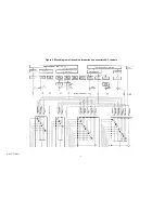
Страница 4: ...Figure 1 Layout of the building blocks in the organ top AM 075 Part 4 ...
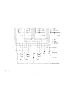
Страница 5: ...Figure 2 Block diagram of the audio distribution and associated DC controls AM 075 Part 5 ...
Страница 6: ...AM 075 Part 6 ...
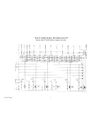
Страница 33: ...Figure 4 Schematic layout of the wiring harness GO 4 AM 075 Part 33 ...


