The testing and adjustments of the special effects is treated in the
assembly manual AM 400.
1. Mate the connectors with the pins of the U /Man special
effects, referring to Fig. 81.
2. Push the drawbar preset board PZ 6 onto the round pins on
the special effects drawbars P Z 6 and mate the connector of
branch 7.4 with the pins on PZ 6, referring to Fig. 84.
3. Test the operation of the U /Man special effects, in
conjunction with the 20 associated rocker switches on the
stop board, referring to the manual AM 400. The slide
controls are located among the grey draw bars and the
associated "Manual Wah Wah" control is part of the left
control panel.
Note: The U/Man special effects do not pass any channel selectors.
However, they sound from the right channel if no Wersivoice is
used and from the left speaker if the Wersivoice is treating the
audio signal.
3.21 Testing of the M/Man Special Effects
1. Mate the connectors with the pins of the M/Man special
effects, referring to Fig. 80.
2. Test all modes of operation of the M /Man special effects.
The associated switches and controls are located on the
right control panel (except the master volume control which
is a grey drawbar on the left side).
Note: No drawbars are assigned to the M/Man special effects and
only 16 control switches are used. The switches which are missing
with respect to the U /Man special effects are:
a) " Drawbars": Only preset 2nd and 3rd harmonics can
be selected but not manually settable drawbars.
b) "Fast Rate", "Medium Rate" and "Short Rate": The
special effects rate is "slow" as tong as the button
"Variable Rate" is released. Depressing the latter
button activates the rotary control "Spec. Eff. Rate" on
the right control panel.
The special effects audio signals of the M /Man are either fed
directly to the left channel (button "Spec. Eff. to Wersivoice"
released) or to the Wersivoice I ("Spec. Eff. to Wersivoice"
depressed). When channelled through the Wersivoice, the audio
signal may be channel-selected by the rocker tab "Wersivoice I
right/left".
3.22 Testing of the Piano
1. Mate the connectors to the pins of the piano voicing board PI
1 as shown in Fig. 72.
2. Pull the volume drawbar "Piano" (grey drawbar) halfway.
3. Perform the tests and adjustments on the piano section,
referring to the assembly manual AM 420. After the
adjustment of the tremolo modulator, check the individual
voices. Verify the operation of the drawbar type control
"Tremolo Speed" (grey drawbar) in connection with the
rocker tab switches "Echo" and "Tremolo" respectively. The
speed of either operating mode should increase as the grey
drawbar” Tremolo Speed" is pulled out.
Check the operation of the "Long Sustain" switch and check
whether the left-hand foot lever on the swell pedal produces
long sustain too(independently of the position of the "Long
Sustain" switch).
AM 075 (Part)
26
Содержание GALAXY
Страница 1: ...Master Assembly GALAXY AM 075 AM 075 Part 1 ...
Страница 4: ...Figure 1 Layout of the building blocks in the organ top AM 075 Part 4 ...
Страница 5: ...Figure 2 Block diagram of the audio distribution and associated DC controls AM 075 Part 5 ...
Страница 6: ...AM 075 Part 6 ...
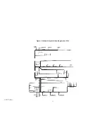
Страница 33: ...Figure 4 Schematic layout of the wiring harness GO 4 AM 075 Part 33 ...


