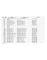
Wire
Type/
Starts at:
Ends at:
Use, Remarks
No.
Color
(Subunit, PC board, terminal)
(Subunit, PC board, terminal)
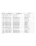
144a S,gn
M/M fixed stops, G P 1, plug 2, cond.to
pin Outp.,shield to G N D
M/M spec. effects, E F 1, cond.to pin 13,shieldjoined with
144b
M/M fixed stops audio to M/M spec. effects
144b S,gn
M/M spec. effects, E F 1, cond.to pin
13,shield cut off
M/M spec. effects, E F 1, cond.to pin 20, shield joined with
144a
Extension of 144a
145 W,gy
M/M fixed stops, GP 1,plug 1, pin SIN-
VV
Channel selectors, S 4 K,point8
M/M drawbars to ch. sel.
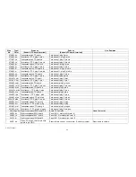
146 W,ye/bn Channel selectors, S 4 K, point 7
Right preamp, VV 2, plug 4, pin S3
M /M drawbars to right preamp
147 W, yell
Channel selectors, S 4 K, point 9
Left preamp, V V 2, plug 4, pin S 3
M/M drawbars to left preamp
148 W, yell
M/M fixed stops, GP 1, plug 1, pin SIN-
WV
Wersivoice I, WV 7, pin 1c
M/M drawbars to Wersivoice I
149 W,gn/r
M/M fixed stops, G P 1, plug 1, pin F R-
VV
Channel selectors,S 4 K, point 11
M/M & U/M Il to ch. sel.
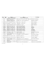
150 W,ye/bk Channel selectors,S 4 K, point 12
Right preamp, VV 2, plug 4, pin S4
M/M & U/M Il to 'right preamp
151 W,gn/bk Channel selectors, S 4 K,point10
Left preamp,V V 2, plug 4, pin S4
M/M & U/M Il to left preamp
152 VC gn/bk
M/M fixed stops, GP1, plug1, pin F R-
WV
Wersivoice1,WV 7, pin 2c
M/M & U/Mll to Wersivoice I
153 W,bn
U/M Il fixed stops, board DS 1, plug 1,
pin 3
Right control panel, SW 6, point 3
Control voltage for orchestra coupler
154 S,gy
U/M I fixed stops, GP 1, plug 2, cond.to
pin Outp.,shield to G N D
U/M volume control, cond.to term. E, shield to jumper
U /M I fixed stops audio to volume control
155a S,gy
U/M volume control, cond.to term. S,
shield to term. A
Right preamp, VV 2, plug 3, cond.to pin E2, shield cut off U/M I fixed stops audio to both preamps
155b S,gy
U/M volume control, cond. to term. S,
shield to term. A
Wersivoice II, WV 7, cond.to pin 2, shield cut off
U/M I fixed stops audio to Wersivoice II
AM 075 (Part)
41
Содержание GALAXY
Страница 1: ...Master Assembly GALAXY AM 075 AM 075 Part 1 ...
Страница 4: ...Figure 1 Layout of the building blocks in the organ top AM 075 Part 4 ...
Страница 5: ...Figure 2 Block diagram of the audio distribution and associated DC controls AM 075 Part 5 ...
Страница 6: ...AM 075 Part 6 ...
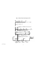
Страница 33: ...Figure 4 Schematic layout of the wiring harness GO 4 AM 075 Part 33 ...


