will, at best, knock you off your feet, and, at worst, destroy
the amplifier and the speaker.
Run your test finger along the G 2 boards of the other tone
generator too. The tones you hear indicate that both
generators deserve their prefix (namely tone...)
3. The same "test finger" method can also be used to verify that
the electronic keyers and the envelope control boards are
working. Leave the bare wire end connected at "A 2'; plug 5,
of either preamplifier. Hold the other end with one hand and
touch the pins "Sq " or "Sin" of the E T 13 boards (on keyer
block) with a finger of the other hand while holding down one
or more keys. Obviously, the keys of the lower manual are to
be depressed when touching the outputs of the L/Man
keyers Tones at different pitches should be heard when
touching the output pins of different footages.
Repeat this test for the other two manuals and keyers
respectively.
Remove the audio monitor lead from the location "A 2" on
the preamplifier. Save the lead for future use. Turn off the
organ.
3.5 Testing of the Lower Manual Drawbars
1. Pull all drawbars of the lower manual halfway.
2. Locate the pre-assembled drawbar preset board P Z 4
(L/Man) and push it onto the round pins of the L/Man
drawbar board Z R 4.
3. Mate the connector attached to branch 7.3 of the harness G
O 4 with the pins of plug 1 on the board P Z 4 (L/Man),
referring to Fig. 84.
4. Turn on the organ. Depress a key near the centre of the
lower manual and hold it depressed. (Wedge some non-
metallic material between the key and the manual spacer.) N
o tone should be heard yet.
5. Clip the test lead (-15 V) to pin " S 5'; plug 4, of the right
preamplifier. ("S 5" is the control input for the audio input "E
5" where the audio signal from the L/Man drawbars arrives -
see Fig. 65.)
6. The drawbar signal should be audible from the right speaker.
Adjust the trim pot P 5 "Volume" on the right preamplifier VV
1 to obtain a satisfactory listening level.
Possible problems
: The (mixed) drawbar signal is not audible.
Possible causes:
The input gate responsible for the input E 5 on the
right preamplifier is not working properly or the audio signal from
the L/Man drawbars does not arrive at pin E 5.
Trouble-shooting:
Push the saved lead with the bare wire into the
opening, corresponding to pin " E 5 " of the right preamplifier.
Leave the test lead (-15 V) clipped to S5. Hold the other end of the
audio monitor lead with one hand (you may hear hum) and touch
the input pins on the L/Man drawbars one by one (the14-conductor
cable is attached to these pins). The tones from the various
footages should be heard. If not, the trouble is located tin the
preamplifier (either associated with the input gate E 5/S 5 or the
AM 075 (Part)
11
Содержание GALAXY
Страница 1: ...Master Assembly GALAXY AM 075 AM 075 Part 1 ...
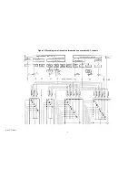
Страница 4: ...Figure 1 Layout of the building blocks in the organ top AM 075 Part 4 ...
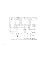
Страница 5: ...Figure 2 Block diagram of the audio distribution and associated DC controls AM 075 Part 5 ...
Страница 6: ...AM 075 Part 6 ...
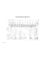
Страница 33: ...Figure 4 Schematic layout of the wiring harness GO 4 AM 075 Part 33 ...


