3 Initial Operation
We presume that the power supply, the tone generators, the
electronic keyers, the envelope control, as well as the power
chassis, have passed their respective testing successfully earlier.
As a reminder, the harness P R 4 must not be installed yet at this
point in time. If it is installed (against our recommendations) do not
mate any connectors to the sound computer boards SC 3 and SC 5
respectively.
We further presume that the harness G04 was wired exactly as
described earlier in this manual. Only a limited number of
connectors should be mated at this time. Others are not connected
yet.
NOTE-IMPORTANT
Refer to Fig. 91. Remember that you have joined the 5 blue wires in
the vicinity of the "Read-in" key switch and that all " PM ..." lines
were joined with the respective blue wires. This applies an
unconditional negative control voltage to all tab and rocker switches
of the organ, that is, the organ is permanently under manual
control. When you will be ready to install the sound computer, these
temporary connections will have to be eliminated.
3.1 Test Lead
1. Cut a 40" long piece of thin hookup wire and attach a
connector insert to one end. Push this insert into a free
position of one of the -15 V connectors on the power supply.
(Many blue wires are already connected there.)
2. Attach an alligator clip to the other end of the test lead. We
are going to call this wire simply "Test lead" in the future.
Never allow the alligator clip to touch ground (all black wires
and metal chassis parts respectively) nor +1 5 V (all red
wires).
As you may have noticed by now, all functions of the organ are
controlled by a negative control voltage. This control voltage may
stem from a front panel switch, from the sound computer, or from
our test lead.
The conversion of this control voltage into the respective function
normally takes place directly on the circuit board where that
function is located.
Examples: Electronic input gates on the preamplifier board V V 2
determine whether a particular audio signal
is to be passed on to the circuitry or not. Electronic switches select
the voices on the piano voicing board PI 1. D C controlled field
effect transistors (F E T) activate the fixed stops. Logic circuits
determine the modes and speeds of the Wersivoice.
We may use the test lead to by-pass any switches and activate a
particular function directly by applying -15 V directly to a control
input terminal. Should you encounter a function which is inoperative
when the corresponding switch is activated, the trouble-shooting
procedure is straightforward. In that case, consult the wire list for
the harness G O 4. There you find the wire number between the
switch in question and the corresponding control port. Apply the
test lead to that control terminal. If the function is now operative, the
trouble is limited to the wiring (check colours) or the switch (solder
connections, associated diode). If the function remains non-
AM 075 (Part)
8
Содержание GALAXY
Страница 1: ...Master Assembly GALAXY AM 075 AM 075 Part 1 ...
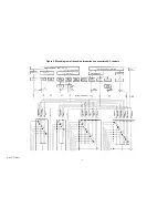
Страница 4: ...Figure 1 Layout of the building blocks in the organ top AM 075 Part 4 ...
Страница 5: ...Figure 2 Block diagram of the audio distribution and associated DC controls AM 075 Part 5 ...
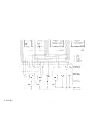
Страница 6: ...AM 075 Part 6 ...
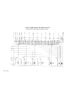
Страница 33: ...Figure 4 Schematic layout of the wiring harness GO 4 AM 075 Part 33 ...


