


39
WAS.handling Windows – Program
5.2
Configuration of axes
In the
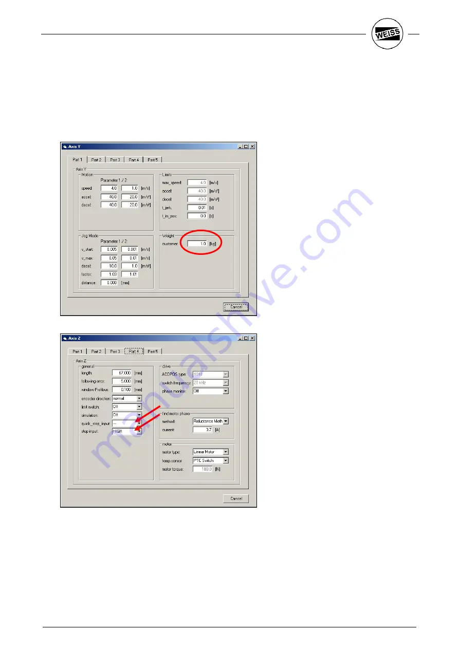
Tools – Y axis
menu open the dialog for parameterizing the Y axis. Enter the weight of the g
workpiece into
Load – Customer
and confirm by pressing ENTER. Accelerations are adjusted automatically.
If you have already wired the Quickstop input (terminal X1/2) of the drive, switch to part 4 and specify,
whether the input should be HIGH or LOW active.
If an HP140 with shortened horizontal axis is used, check the
Length
parameter of the
Y axis
in part 4.
The parameters for Load and Stop / Quickstop are automatically entered for the Z axis.
Содержание WAS.handling
Страница 1: ......
Страница 52: ...49 WAS handling Windows Program...
Страница 58: ...55 WAS handling Windows Program...
Страница 59: ......
Страница 60: ......


