Installation and Operating Manual
Page
32
Printed: 02/2015
6.2. Connection of steam heater
Ensure proper drainage of condensate. To ensure proper control for partial load operation,
each steam battery must be equipped with a separate condensate drain.
6.3. Connection of refrigerant line
Observe the instructions in section 6.1.
Prior to connection, the exchanger and lines must be tested for leakage (to determine whether
the shielding gas is still pressurised).
6.4. Condensate drain
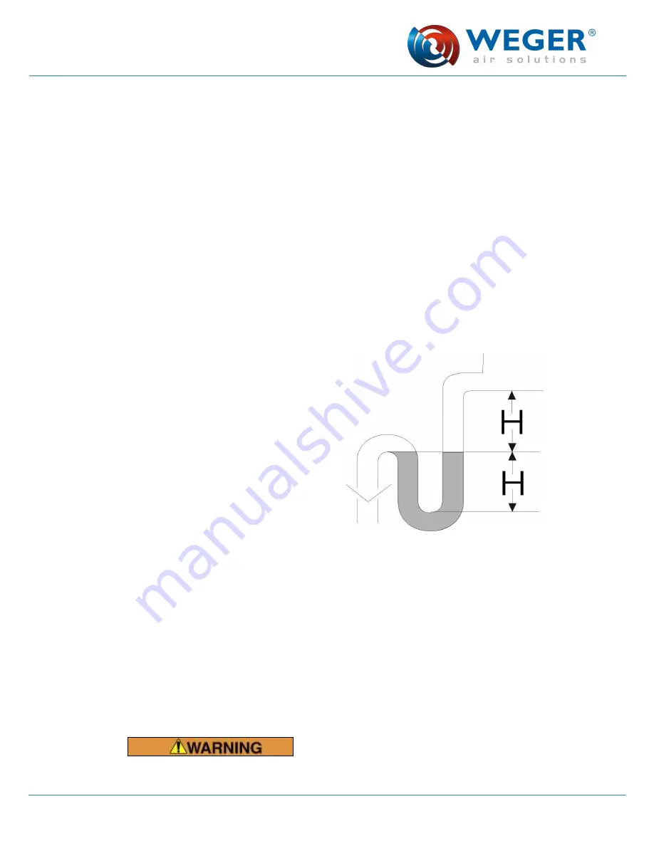
Install a siphon at each drain adapter. The effective head in mm must correspond to the
maximum static internal pressure of the unit (hydrostatic head) + 15 mm.
Example:
Total effective pressure = 1196 Pa (see data
sheet)
Dynamic effective pressure = 2 x 83 Pa (see
data sheet)
Total effective pressure - dynamic effective
pressure = Pstat = 1030 Pa
1 mm hydrostatic head = 9.81 Pa
H = 1030 / 9.81 + 15 mm
= 120 mm
The connecting line for condensate must have a diameter of minimum 40 mm and be
equipped with a siphon with backflow protection. It must feature an exposed outlet to the
waste water system but must not be directly connected to it. Outlets at different pressure
levels must be equipped with separate siphons.
6.5. Air duct connections
The air duct connections to the unit must be free of stress and air-tight. To prevent
propagation of structural vibration, we recommend installing elastic connecting adapters or
insulating connecting frames that are mounted without stress between the unit and the duct.
Risk of injury from electric shock! Install all necessary earthing conductors/potential
equalization equipment.
Содержание DIWER EVO DP80 Series
Страница 2: ......
Страница 39: ...Installation and Operating Manual Page 37 Printed 02 2015...
Страница 62: ...Installation and Operating Manual Page 60 Printed 02 2015 Notes...
Страница 63: ...Installation and Operating Manual Page 61 Printed 02 2015 Notes...
Страница 64: ...Installation and Operating Manual Page 62 Printed 02 2015 Notes...


