English
TROUBLESHOOTING AND MAINTENANCE
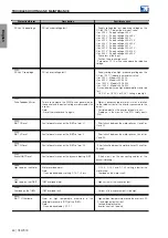
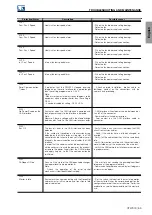
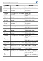
Protection/Alarm
Description
Possible causes
F078:
Motor Overtemp.
Fault related to the PTC temperature sensor installed
on the motor.
Note:
- The fault can be disabled by setting C7.5.2 = 2 or
3.
- It is necessary to program Slot X analog input and
output for PTC function.
- Load on the motor shaft is too high.
- Load cycle is too short (high number of starts and
stops per minute).
High ambient temperature around the motor.
- Poor contact or short circuit (resistance < 100 Ω) on
the wiring connected to the motor thermistor.
Motor thermistor not installed.
- Motor shaft locked.
F080:
CPU Fault (Watchdog)
Inverter control watchdog fault.
- Electrical noise.
F084:
Self-Diagnostics. Error
Self-Diagnostics Fault.
- Defect on the inverter internal circuits.
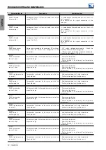
A090:
External Alarm
External alarm via DI.
Note:
- Necessary to set the DI in C7.10.1.
- DI input wiring (set in C7.10.1 to generate external
alarm) open.
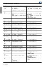
F091:
External Protection
External fault via DI.
Note:
- Necessary to set the DI in C7.10.2.
- DI input wiring (set in C7.10.2 to generate external
fault) open.
F099:
Invalid Curr. Offset
Current measurement circuit has a value out of the
standards for zero current.
- Defect on the inverter internal circuits.
F104:
A/D Converter Error
Fault reading the A/D converter that measures the
inverter currents and voltages.
- Defect on the inverter internal circuits.
- Electromagnetic interference above the level the
inverter withstands.
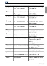
A110:
High Motor Temperature
Alarm related to the PTC temperature sensor installed
on the motor.
Note:
- The alarm can be disabled by setting C7.5.2.
- It is necessary to program Slot X analog input and
output for PTC function.
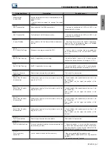
- Load on the motor shaft is too high.
- Load cycle is too short (high number of starts and
stops per minute).
High ambient temperature around the motor.
- Poor contact or short circuit (resistance < 100 Ω) on
the wiring connected to the motor thermistor.
Motor thermistor not installed.
- Motor shaft locked.
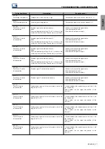
A128:
Serial Communication
Timeout
It indicates that the CFW900 stopped receiving
telegrams on the serial interface for a period longer
than the setting programmed in C9.3.5.
Note:
- Make sure the master always sends telegrams to the
equipment within a period shorter than the setting in
C9.3.5..
- It can be disabled by setting C9.3.5=0.0 s.
- Check network installation, broken cable or
fault/poor contact on the connections with the
network, and grounding.
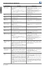
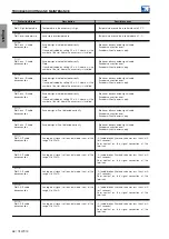
A133:
No Power Supply on the
CAN Interface
It actuates when the CAN interface is powered and
lack of power supply to the interface is detected.
Note:
Measure if there is voltage within the allowed range
between pins 1 and 5 of the CAN interface connector.
- CAN interface without power supply between pins
1 and 5 of the connector.
- Power cables switched or reversed.
- Poor contact on the CAN interface cable or
connector.
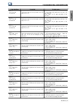
A134:
Bus Off
The bus off error in the CAN interface has been
detected.
If the number of reception or transmission errors
detected by the CAN interface is too high, the CAN
controller can be taken to the bus off state, where it
interrupts the communication and disables the CAN
interface.
In order that the communication be reestablished, it
will be necessary to cycle the power of the product,
or remove the power supply from the CAN interface
and apply it again, so that the communication be
reinitiated.
- Verify if there is any short-circuit between the CAN
circuit transmission cables.
- Verify if the cables have not been changed or
inverted.
- Verify if all the network devices use the same baud
rate.
- Verify if termination resistors with the correct values
were installed only at the extremes of the main bus.
- Verify if the CAN network installation was carried out
in proper manner.
62 | CFW900

