English
INSTALLATION AND CONNECTION
3.3.2 Conformal Installation
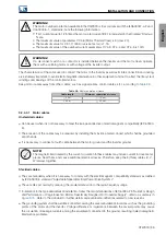
For conformal installation, you must:
1. For TT/TN supply networks, keep the internal RFI filter connected.
2. Shielded output cables (motor cables) with the shield connected on both sides, motor and inverter, with
low impedance connection for high frequency; for example, see
. Keep the separation from the
other cables according to Table 3.9. For more information see
. Maximum motor cable length and
conduced and radiated emission levels according to
.
3. Ground the inverter as explained in
.
4. Use shielded control cables and keep the separation from the other cables according to
.
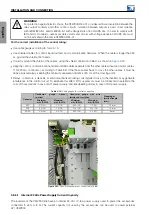
5. Design or choose the panel considering the applicable measures to comply with the EMC standards. If
an extension is made inside the panel for connecting the power, motor and ground cables (that is, if these
cables are not directly connected to the inverter terminals), the panel must be designed so as to have a low
impedance connection for high frequencies. In this case, it is not necessary to use a shielded cable between
the inverter UVW terminals and the connection points of the motor shielded connection cable; however, it is
necessary to provide a way to ground the cable shield with a 360° connection in a similar way to the one
found in the inverter cable grounding kit supplied with the inverter.
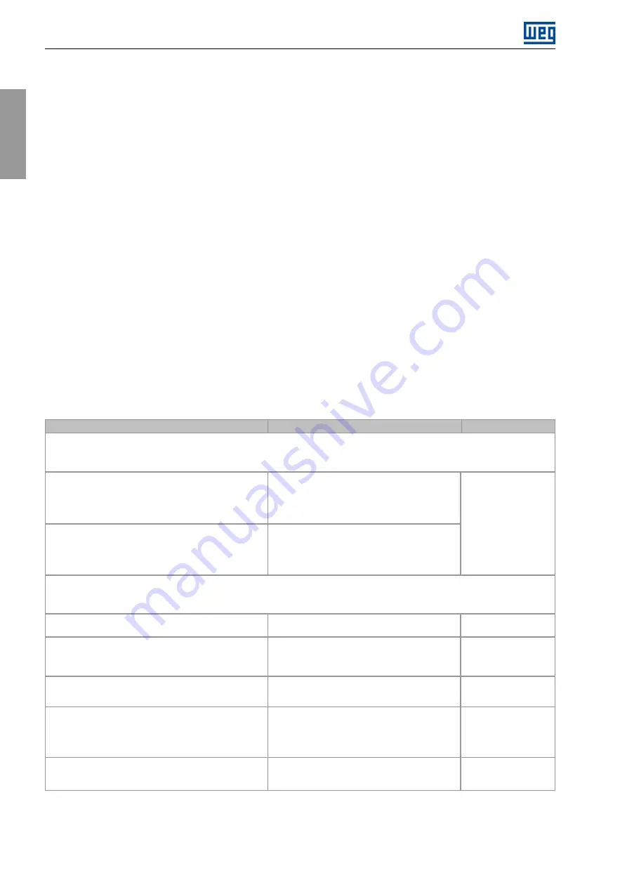
3.3.3 Emission and Immunity Levels Met
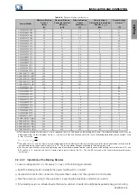
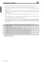
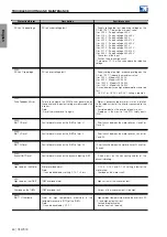
Table 3.18:
Emission and immunity levels
EMC PHENOMENON
LEVEL
BASIC STANDARD
Emission
Mains terminal disturbance voltage
Frequency range: 150 kHz to 30 MHz
Category C2: maximum 10 m cable in TT/TN
networks
(1)(2)
Category C3: maximum 200 m cable in TT/TN
networks
Category C4: IT or delta earthed networks
IEC/EN 61800-3:2017
Electromagnetic radiation disturbance
Frequency range: 30 MHz to 1 GHz
1.4 GHz to 2.7 GHz
Category C3 in TT/TN networks
(All frame D models require a panel with minimum
attenuation of 10dB to comply with the C3
category)
Category C4: IT or delta earthed network
Immunity
Electrostatic discharge immunity test
4 kV for contact discharge and 8 kV for air
discharge
IEC 61000-4-2
Electrical Fast Transient/Burst immunity test
2 kV/5 kHz (coupling capacitor) input cables,
control cables and motor cable
1 kV/5 kHz (coupling capacitor) remote HMI cable
IEC 61000-4-4
Immunity to conducted disturbances induced by radio-
frequency fields
0.15 to 80 MHz; 10 V; 80 % AM (1 kHz)
Motor, control and remote HMI cables
IEC 61000-4-6
Surge immunity test
1.2/50 µs, 8/20 µs
1 kV input cables, line-to-line coupling
2 kV input cables, line-to-ground coupling
1 kV control cables, coupling to the cable shield,
cable shield grounded at both ends
IEC 61000-4-5
Radiated, radio-frequency, electromagnetic field immunity
test
8 a 1000 MHz
10 V/m
80 % AM (1 kHz)
IEC61000-4-3
(1)
Use of toroid on power cables is required (Part Number T60006-L2045-V101-01- VACUUMSCHMELZE manufacturer or similar).
(2)
The models with frames C, D and E of line T2 and frame E of line T4 do not comply with the C2 category.
46 | CFW900


