English
INSTALLATION AND CONNECTION
1
2
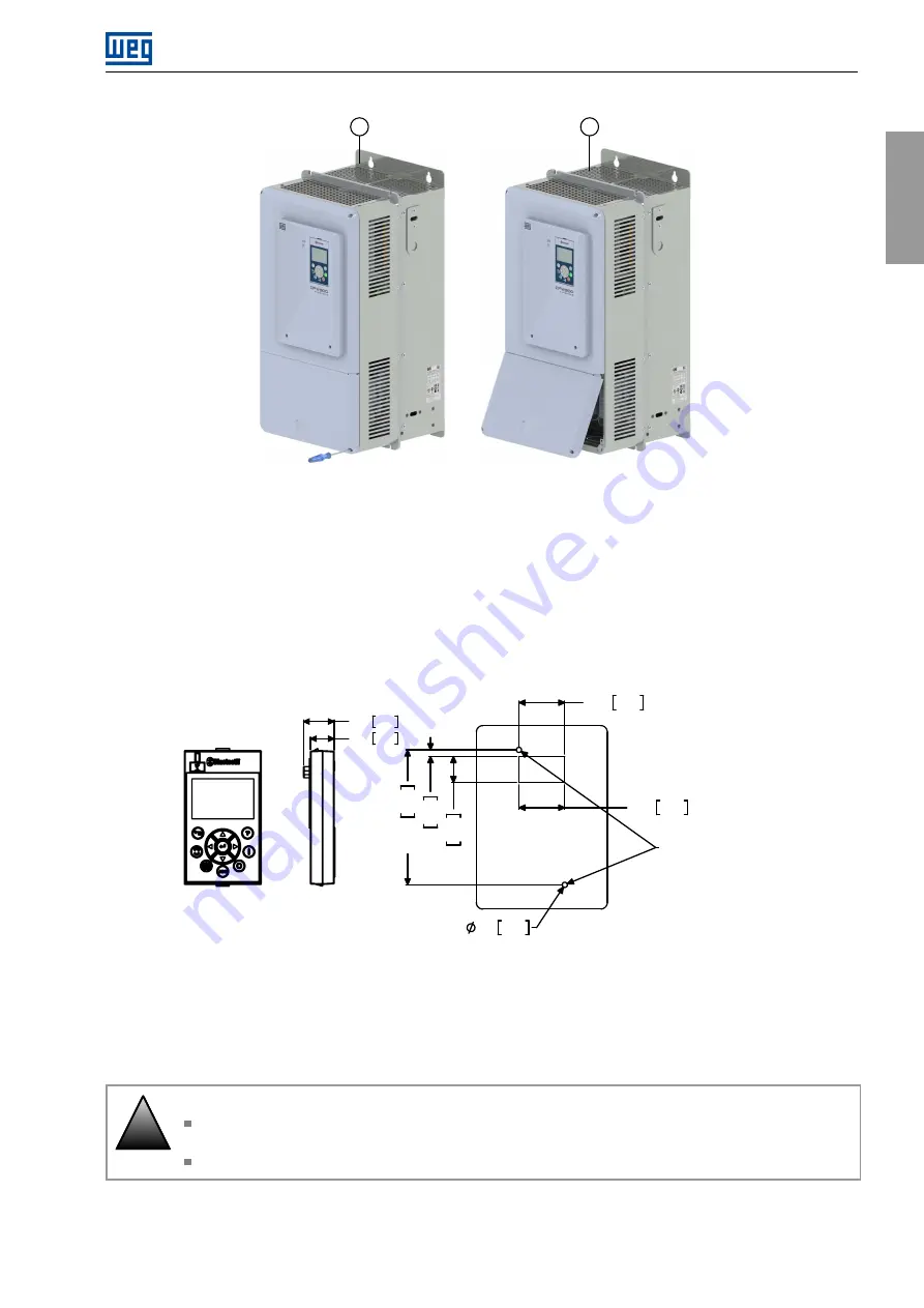
Figure 3.7:
Bottom front cover removal
3.1.6 HMI Installation at the Cabinet Door or Command Panel (Remote HMI)
The dimensions necessary to assemble the HMI on the panel door or control table are shown in
. If you
prefer, the frame accessory can also be used to fix the HMI in these places.
1.38
4.0
5
.0
1.38
35.0
0
.7
9
2
0
.0
4
.0
6
1
0
3
.0
0
.2
0
0.16
35.0
Self-tapping screw for plastic:
Ø3mm / 7mm of maximum length
65.0 [2.56]
25.9 1.02
20.0 0.79
1
13.
0
[4.
45]
Figure 3.8:
Data for the HMI installation at the cabinet door or command panel - mm [in]
3.2 ELECTRICAL INSTALLATION
!
DANGER!
The following information is merely a guide for proper installation. Comply with applicable regulations
for electrical installations.
Make sure the AC power supply is disconnected before starting the installation.
CFW900 | 17


