5 of 11
WX-501-0544 • 01.22
The LED state during the mode selection process can be either flashing or solid. If the current mode is a flashing
mode, the corresponding LED will flash during mode selection. However, after a flashing mode is selected, the
selected mode LED will not flash—the red LED will flash instead.
Navigating the Menu via the Push-Button
The menu is navigated via the push-button using hold and press actions:
■
Hold –
Pressing and then holding for at least 1½ seconds allows you to enter the Click 513 mode selection process.
■
Press –
Pressing and then quickly releasing the push-button allows you to make a selection in the menu.
The menu is used to select and run an application’s operating modes. Select a mode by navigating through the
main menu (multicolored LEDs) and the submenus (yellow and red LEDs) as described below:
1. Enter the main menu by holding the push-button down. Continue holding the push-button to cycle through the
entire menu.
2. Release the push-button once the cycle reaches the desired mode (see the table above).
3. Press the push-button again to select the mode. Once the mode is selected it will start running. If you selected
to reset the device, the submenu of yellow LEDs will start (the first LED will light up).
4. Hold the push-button to cycle through the options of the submenu.
5. Release the push-button once the desired option is displayed.
6. Press the push-button again to select the option. The mode will now start running.
Run Mode (blue solid)
Run mode is the first mode presented in the mode selection process, but usually the second one to be used. It
will first be necessary (at least the first time the device is used) to use Device Setup mode. When the device is in
Device Setup mode, Click Supervisor can be used to configure the device (see the Device Setup Mode section
below). Once that is completed, use the push-button to select
Run
mode (blue solid).
While in Run mode the Click 513 will poll the SmartSensor HD for data from the first and second approaches, and if
the configured conditions are met an output will be triggered.
When you are using a Click 112 or 114 contact closure device, each time the Click 513 triggers an alert on either
approach the corresponding digital output is closed. The top/front RS-485 port of the Click 513 then sends a
message to the attached Click 112 or 114 to close the first or second contact.
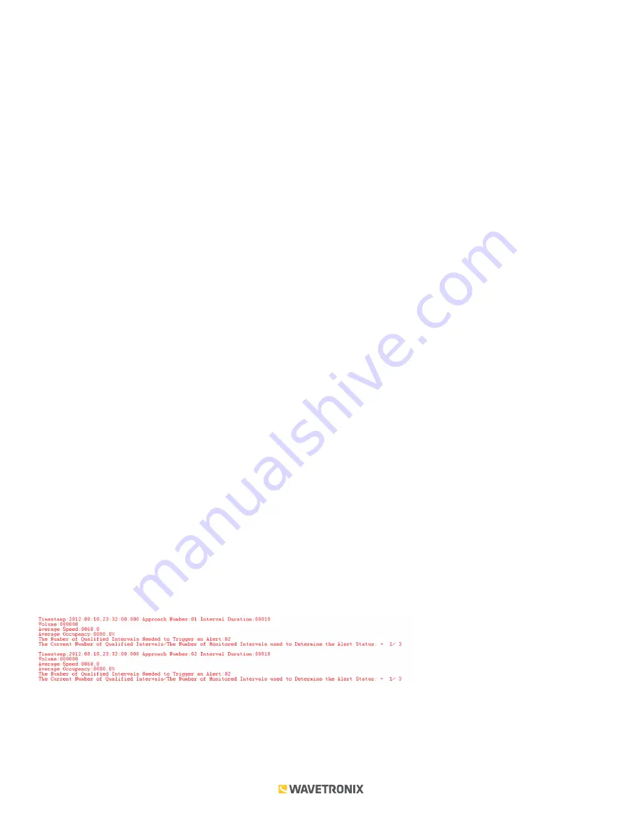
For data verification purposes the event-data messages pushed by SmartSensor HD are translated into readable
text strings. This information is forwarded as ASCII text messages over the RS-232 ports of the Click 513. The
following illustrates an interval detection entry in a terminal program:
Device Setup Mode (green solid)
Device Setup mode is the second mode presented in the mode selection process. This mode allows you to
configure threshold variables and set up communications with the Click 112 or 114.


