background image

30

The system corrosion inhibitor level must be checked (instant on­site test kits are available from 
inhibitor  manufacturers)  and  additional  inhibitor  must  be  added  if  the  system  is  found  to  be 
under­dosed. Refer to the inhibitor manufacturer for further guidance.

Note:  All  product  warranties  will  be  invalidated  if  the  appliance  is  not  serviced  at  least 
annually  or  as  indicated  by  the  user  interface  controller  by  a  Warmflow  or  trained 
technician and details recorded in the service record section of this manual.

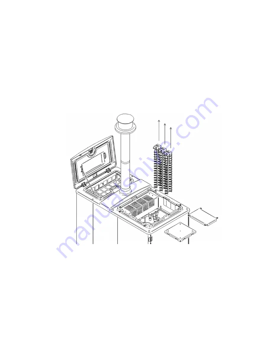
4.2.2 Servicing the heat exchanger 
Before commencing any servicing or maintenance ensure that the mains electrical supply to the 
appliance  is  isolated.  The  mains  electric  isolator  switch  is  located  below  the  main  electronics 
box at the front of the appliance and should be locked by padlock in the off position (see Figure 
1). 

The top of the heat exchanger is accessed by removing the service lid and insulation.
The inspection door and cleaning mechanism door must then be removed to give access to the 
heat exchanger and turbulators as shown in Figure 32.
The  heat  exchanger  and  air  turbulators  must  be  thoroughly  cleaned  to  remove  soot,  fly  ash, 
carbon deposits and any other combustion residues.
The  turbulators  are  mounted  on  a  rocker  shaft  and  can  be  withdrawn  in  pairs  by  lifting  them 
vertically from the heat exchanger tubes.  The turbulators should be brushed with a steel brush 

Figure 32: Turbulator Removal During Heat Exchanger Service.

Содержание WS18

Страница 1: ...P18 For use with ENplus A1 wood pellets only Look for the ENplus A1 symbol Incorporating User Instructions Installation Instructions Service Instructions Guarantee Terms Conditions Registration Docume...

Страница 2: ...tory must be maintained in Section 7 of this manual NI Customers Only Warmflow Engineering customer care NI provides an excellent back up service operating a team of trained engineers who can meet all...

Страница 3: ...ystem 16 3 1 4 Air Vents 17 3 1 5 Drain Cock 17 3 1 6 Pipework 17 3 1 7 Heating System Design 17 3 2 Sealed Systems 17 3 2 1 Expansion Vessel 17 3 2 2 System Filling 18 3 2 3 System Pressure 18 3 2 4...

Страница 4: ...6 APPLIANCE INSTALLATION COMMISSIONING CERTIFICATE REGISTRATION 33 7 APPLIANCE SERVICE RECORDS 35...

Страница 5: ...at all times when not refilling An interlock switch is fitted to the hopper door meaning the appliance will not operate if the hopper door has been left open The service access lid is located on top o...

Страница 6: ...and injury will result The combustion pot is located on the inside of the combustion door and can be removed for servicing and routine maintenance by releasing the toggle latches on either side of the...

Страница 7: ...lean the combustion pot as directed may restrict the flow of air within the appliance adversely affecting its performance Table 1 Product Data Description Model Type WS18 WP18 Wood Pellet Boiler Dimen...

Страница 8: ...he emissions limits for particulate matter and NOx as stated by DEFRA As such the emissions are within the acceptable limit for the appliances to be used in installations wishing to claim the renewabl...

Страница 9: ...1 2 The fuel hopper has a wood pellet capacity of 120kg At maximum output the appliance will run for approximately 30 hours before requiring refilling Therefore the fuel hopper will typically require...

Страница 10: ...n inhibitors in the system water Where there is a need for topping up concentrations must be restored to inhibitor manufacturers recommendations and monitored going forward Frequent or routine topping...

Страница 11: ...run as normal for 1 hour dependent on the heat demand of the property You should fill the hopper within this time Filling the hopper will automatically reset this alert Fuel Level Empty The pellet hop...

Страница 12: ...six options in the main menu including Home Alarms Cleaning Engineer Settings and Help Home Selecting the home menu returns the display to the home screen This display is as shown in Figure 9 and deta...

Страница 13: ...igure 11 below This screen shows the number of days before cleaning is due It will also indicate if cleaning is overdue Pressing the Enter key in this screen activates the cleaning preparation utility...

Страница 14: ...ot should be emptied and cleaned paying particular attention to ensure the small air holes are clean and unblocked The shelf on which the combustion pot is located and which houses the pot grate and c...

Страница 15: ...adjusted by the user The information and setting screens are displayed in the same format as the main menu screen and may be accessed in the same way The sub menus include date time temperature and i...

Страница 16: ...nce has various operating modes see Table 3 Page 13 The appliance has a start up sequence as shown in Figure 20 see page 14 and will only begin firing if there is a heat demand present i e a signal fr...

Страница 17: ...lets in the combustion pot Stabilisation Ensuring that the flame is given time to establish Power band 1 2 3 4 5 Output power determined by heat demand Extinguish Shut down initiated Final Cleaning Cl...

Страница 18: ...18 Engineer Figure 20 Flow Chart...

Страница 19: ...cing engineer and parameters Help Selecting the help menu as shown in Figure 22 below displays the contact details for Warmflow who should be contacted if you require further assistance or if you enco...

Страница 20: ...ugh maximising access is recommended Please refer to local Building Regulations for permissible distances from combustible surfaces If the appliance is intended for internal installation please refer...

Страница 21: ...ork is run in copper However if plastic pipe is used the last 1000mm of pipework connected directly to the appliance must be of copper All connections to the appliance must be made with compression fi...

Страница 22: ...contact Warmflow or your installer Special attention must be given to the concentration of corrosion inhibitors in the system water where there is a need for topping up or refilling Inhibitor concentr...

Страница 23: ...23 The drainage hose must not be affected by any blockage which could lead to condensation backfilling into the heat exchanger of the appliance causing corrosion 3 3 Figure 24 Condensate Trap Plumbing...

Страница 24: ...connection It is advised that the pipe work from the appliance to the interior of the property must be 28mm and insulated with a minimum of 9mm pipe insulation The appliances anti condensation valve i...

Страница 25: ...e other end of the cable with the RJ12 plug connects into the back of the user interface controller supplied 24V pLAN GND Tx Tx 24V pLAN ext GND Solid Green Striped White Blue Striped White Green Soli...

Страница 26: ...d of silicone sealant around the collar prevent water ingress refer to Figure 30 This flue system is adequate only if the flue terminal is more than 2 3 meters from an adjacent wall or surface as requ...

Страница 27: ...27 Figure 30 Flue Assembly...

Страница 28: ...28 4 COMMISSIONING AND SERVICING Figure 31 Flue Outlet Positions for Solid Fuel Appliances...

Страница 29: ...e flue gas temperature is above 140 C or a CO value above 400ppm consistently please contact Warmflow Please refer to Table 1 for flue gas temperatures at maximum and minimum outputs The appliance has...

Страница 30: ...al supply to the appliance is isolated The mains electric isolator switch is located below the main electronics box at the front of the appliance and should be locked by padlock in the off position se...

Страница 31: ...unfastening the seven screws shown in Figure 33 below This will allow access to remove damp pellets or dust from the hopper The end cap of the auger can be removed to allow pellet dust or remaining p...

Страница 32: ...otor must be unplugged and the motor motor bracket and cleaning mechanism must be withdrawn horizontally from the combustion door Next the locating pins must also be withdrawn horizontally allowing th...

Страница 33: ...r conditions of this warranty are met Please note that periods of guarantee will not be extended under any circumstances Warmflow s Obligations Where components are found to be defective in materials...

Страница 34: ...er if required by the variable service schedule in the controller Warmflow reserves the right to determine at its absolute discretion whether a person is appropriately qualified and has suitable train...

Страница 35: ...s or damage that are not the direct fault of Warmflow including without limitation loss or damage caused by any one or more of the following a use of the Boiler in anything other than its normal and i...

Страница 36: ...quate supply of services such as electricity or water to the property Claims for consequential loss or damage however caused are not covered by this guarantee Please note that your statutory rights ar...

Страница 37: ...ly x Ensure that the certificate is signed by both the Competent Person and the Customer x Carbon copies of the certificate are produced automatically x Register the Appliance x Remove the white copy...

Страница 38: ...ioning Performance Commissioning Date Flue Gas Analyser Make Model Calibration Date Fuel Brand ENplus 1 CO2 Concentration CO Concentration ppm Flue Gas Temperature C Draught Pa Fan RPM Efficiency Nett...

Страница 39: ...39 INTENTIONALLY LEFT BLANK...

Страница 40: ...ith the service schedule and instructions laid out in this manual x Details of the service conducted must be fully recorded on the following service record sheets by the competent person conducting th...

Страница 41: ...al Refractory Insulation Frost Protection Heat Exchanger Surfaces Cleaning Appliance Safety Controls Mechanisms Heat Exchanger Seals Corrosion Inhibitor Level 4 System Modifications Since Last Service...

Страница 42: ...al Refractory Insulation Frost Protection Heat Exchanger Surfaces Cleaning Appliance Safety Controls Mechanisms Heat Exchanger Seals Corrosion Inhibitor Level 4 System Modifications Since Last Service...

Страница 43: ...al Refractory Insulation Frost Protection Heat Exchanger Surfaces Cleaning Appliance Safety Controls Mechanisms Heat Exchanger Seals Corrosion Inhibitor Level 4 System Modifications Since Last Service...

Страница 44: ...al Refractory Insulation Frost Protection Heat Exchanger Surfaces Cleaning Appliance Safety Controls Mechanisms Heat Exchanger Seals Corrosion Inhibitor Level 4 System Modifications Since Last Service...

Страница 45: ...al Refractory Insulation Frost Protection Heat Exchanger Surfaces Cleaning Appliance Safety Controls Mechanisms Heat Exchanger Seals Corrosion Inhibitor Level 4 System Modifications Since Last Service...

Страница 46: ...al Refractory Insulation Frost Protection Heat Exchanger Surfaces Cleaning Appliance Safety Controls Mechanisms Heat Exchanger Seals Corrosion Inhibitor Level 4 System Modifications Since Last Service...

Страница 47: ...al Refractory Insulation Frost Protection Heat Exchanger Surfaces Cleaning Appliance Safety Controls Mechanisms Heat Exchanger Seals Corrosion Inhibitor Level 4 System Modifications Since Last Service...

Страница 48: ...al Refractory Insulation Frost Protection Heat Exchanger Surfaces Cleaning Appliance Safety Controls Mechanisms Heat Exchanger Seals Corrosion Inhibitor Level 4 System Modifications Since Last Service...

Страница 49: ...al Refractory Insulation Frost Protection Heat Exchanger Surfaces Cleaning Appliance Safety Controls Mechanisms Heat Exchanger Seals Corrosion Inhibitor Level 4 System Modifications Since Last Service...

Страница 50: ...al Refractory Insulation Frost Protection Heat Exchanger Surfaces Cleaning Appliance Safety Controls Mechanisms Heat Exchanger Seals Corrosion Inhibitor Level 4 System Modifications Since Last Service...

Страница 51: ...accurate at the date of printing E OE but will be superseded and should be disregarded if specifications and or appearances are changed in the interests of continued product improvement CODE 4220 ISS...

Отзывы: