


29
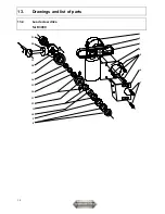
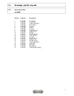
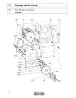
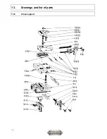
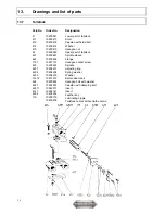
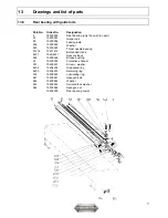
13.
Drawings and list of parts
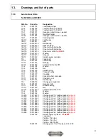
13.3
Lead screw drive
for D2400 and D3000
Part-No. Order-No.
Designation
1119 10201119 Lubricating
nipple
1145
10201145
Toothed belt Z 120 XL037
1146
10201146
Toothed belt Z 140 XL037
1147
10201147
Hexagon socket screw + washer
1149 10201149 Quadrant
holder
11491
10211491
Hexagon socket screw + washer
1261 10201261 Clamping
piece
126111 102126111 Feather
key
12611 10212611 Axis
126112 102126112 Ball
bearing
126113 102126113 Spacer
sleeve
126114
102126114
Drive belt with belt pulley
126115
102126115
Drive belt with belt pulley
126118 102126118 Drive belt J 8-559
for D2400
126116 102126116 Washer
126117 102126117 Stop
nut
12612
10212612
Spindle guide, complete
112 10200112 Feed
shaft
11212 10211212 Feather
key
11213 10211213 Bushing
11214
10211214
Toothed belt pulley Z48
1122 10201122 Washer
1123 10201123 Nut
1125 10201125 Adjusting
ring
1126 10201126 Pressure
spring
1127 10201127 Coupling
1131
10201131
Eccentric shaft, complete
11311
10211311
Stud bolt + nut
11315 10211315 Ball
bearing
114
10200114
Change gear quadrant
1141 10201141 Hexagon
bolt
11411 10211411 Bronze
bushing
11215 10211215 Nut
114114
102114114
Toothed belt wheel Z 14
1142 10201142 Washer
1143 10201143 Washer
114816
102114816
Change gear Z16 (without picture)
optional
114818
102114818
Change gear Z18 (without picture)
optional
114820
102114820
Change gear Z20 (without picture)
optional
114822
102114822
Change gear Z22 (without picture)
optional
114824
102114824
Change gear Z24 (without picture)
optional
114828
102114828
Change gear Z28 (without picture)
optional
114832
102114832
Change gear Z32 (without picture)
optional
114834
102114834
Change gear Z34 (without picture)
optional
114836
102114836
Change gear Z36 (without picture)
optional
114840
102114840
Change gear Z40 (without picture)
optional
10201100
Belt set compl. 5 pieces
for D2400
consists of:
Part-No. 1145 (2x)
Part-No. 1146 (1x)
Part-No. 126118 (2x)
10201101
Change gears 1 set 10 pieces Z16 - Z40
Содержание D2400
Страница 5: ...5 1 Machine dimensions 1 1 D2000 1 2 D2400...
Страница 6: ...6 1 Machine dimensions 1 3 D3000...
Страница 28: ...28 13 Drawings and list of parts 13 3 Lead screw drive for D2400 and D3000...
Страница 32: ...32 13 Drawings and list of parts 13 5 Drive with gear transmission for D2000...
Страница 34: ...34 13 Drawings and list of parts 13 6 Cross support...


