24
11
.
Lubrication coolant unit
The lubrication coolant unit consists of:
1. Tray with lubrication coolant tank which supplies the feed pump with lubrication coolant. General
content of 19 litres.
2. Feed pump with the following electrical data
- nominal voltage 230 V
- frequency 50 Hz
- nominal current input 0.4A
- nominal output 0.07 kW
- ON-OFF switch and mains supply with a length of 2 m with earthed plug.
3. Adjustable, flexible pressure hose with stop valve and nozzle for transporting the cooling lubricant
to the machining area.
When using lubrication coolant, especially water based emulsions, a number of health and safety
measures must be observed, which we would like to recommend:
1. Use concentrated products free of nitrites.
2. Use concentrates without secondary amins.
3. Use products with the lowest possible allergy potential.
When mixing a refill of cooling lubricant, please observe the following:
•
clean / rinse the circulation system (tray / filter)
•
determine the concentration necessary to meet the technical demands
•
(concentrate: water 1:5 – 1:30)
•
check the water has a low level of nitrites (< 50 mg NO 3-, test strip)
A cleaning plan should determine at what intervals the system should be cleaned of swarf and other
waste.
A service plan should determine the following:
•
when to check the concentration in use (daily / weekly)
•
when to check the pH values (weekly)
•
when to check / assess the bacteria count (monthly)
•
when to check the nitrate content (weekly)
(The information in brackets can be varied according to the production circumstances.
In order to reduce splashing, we recommend the attachment of a splash guard and / or reducing the
amount sprayed from the nozzle.
Since steps to protect the skin must be taken, it is advisable to wear gloves and aprons. The skin
should be cleaned with acidic syndets without abrasive ingredients and rich cream should be applied
to regenerate the skin.
Please also take note of the enclosed information on the general operating instructions.
Содержание D2400
Страница 5: ...5 1 Machine dimensions 1 1 D2000 1 2 D2400...
Страница 6: ...6 1 Machine dimensions 1 3 D3000...
Страница 28: ...28 13 Drawings and list of parts 13 3 Lead screw drive for D2400 and D3000...
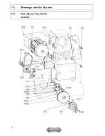
Страница 32: ...32 13 Drawings and list of parts 13 5 Drive with gear transmission for D2000...
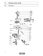
Страница 34: ...34 13 Drawings and list of parts 13 6 Cross support...

