31
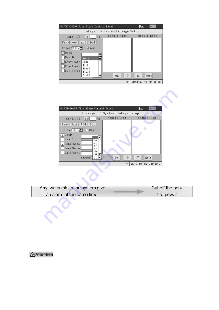
Figure 4-36 Selection of input type
The 5 types commonly used by the system are presented by check boxes and 4 drop-down
selection boxes are given for selection of any equipment type. If the types to be selected exceed
9, a linkage condition can be set additionally, pointing to the same output results.
The selection of linkage alarms is as shown in the figure below:
Figure 4-37 Linkage alarm selection
The default value of linkage alarm is 01, which means the condition is satisfied when any
one equipment reports alarm. In some applications, the following linkage relations may be
possible due to high reliability requirement of linkage action:
At this moment, set the linkage alarm number as 02 and consider the module controlling
"fire pump" as the output result, after that, the linkage relation is completely set. The system
supports complex linkage of any 99 points at most.
A complete linkage condition must include the following element:
Complete zone condition (for example, the room linage must include start room
number and end room number)
Type condition (that is, at least one equipment of a certain type is checked)
Delay time
Output result (that is, at least one module is requested for action when the condition is
satisfied)
If the user input these elements incorrectly during setup, the system will deny and present
corresponding prompt when OK button is pressed.
For secondary trigger of linkage:
Two equipment types will be triggered secondarily according to actual application
requirements of the system:
Far sound equipment
Note: The so-called "secondary trigger" means that when an activated module is
stopped manually and the linkage condition is satisfied again due to new fire alarm,


