VRG CONTROLS LLC.
29 of 39
MAY 2021
RCVC 3000 - Red Circle Valve Controller
Installation, Operation, Maintenance Manual
Страница 1: ... TOLL FREE 800 844 FLOW VRG E MAIL sales vrgcontrols com WEBSITE vrgcontrols com STAY IN TOUCH Scan the QR Code at right for company information and product updates VPC SN SERIES VALVE PILOT CONTROLLER INSTRUCTION MANUAL PATENT NO US 9 400 060 B2 VPC PED ATEX Tag Proof 3 Extreme Tough 3 05 x 1 84 OCTOBER 25 2019 PATENT NO US 9 400 060 B2 US 10 234 047 B2 RCVC 3000 INSTRUCTION MANUAL Applicable Mod...
Страница 2: ...ing Diagram Remote RCVC with Balluff Model BTL 5 Linear Sensor 24 Balluff Calibration 25 29 Figure 7 Spring to Open Ball Control Valve with RCVC VMO Balluff TRM XA 6015 AP01 30 Figure 8 Spring to Open Ball Control Valve with RCVC VMO Balluff TRM XA 6018 AP01 31 Figure 9 Spring to Open Ball Control Valve with RCVC VMO Balluff TRM Fail Closed 32 Figure 10 Spring to Open Glove Control Valve with RCVC...
Страница 3: ...ote Command and Remote Override using 24VDC Technical Assistance Should you have any questions you may contact your local VRG Controls sales representative or VRG Controls technical assistance at VRG Controls Attn 1199 Flex Court Lake Zurich IL 60047 Toll Free 844 FLOW VRG 844 356 9874 Tel 1 847 778 6740 e mail sales vrgcontrols com websight www vrgcontrols com To facilitate requests for technical...
Страница 4: ... Digital Inputs No Digital Inputs 2 Configurable Voltage 24 VDC Input Current 5 0 mAmps Digital Outputs No Digital Outputs 3 Open Sol Close Sol Auxiliary Voltage 24 VDC Load Current max 250 mAmp Analogue Inputs No Analogue Inputs 2 Feedback Command Input Type Current Voltage Voltage Input Range 1 5 0 VDC Voltage Input Impedance 100 kOhms Current Input Range 4 20 mA Current Input Impedance 300 Ohms...
Страница 5: ...Navigation Wheel AWAY CW to increase valve position percentage 4 Rotate Navigation Wheel to NEUTRAL center position to hold position 5 Rotate Navigation Wheel Toward CCW to decrease valve position percentage 6 Rotate Navigation Wheel to NEUTRAL center position to hold position 7 Return Navigation Wheel to Neutral Center Rotation Position SHORT PUSH Navigation Wheel on RCVC Head to exit Manual mode...
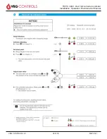
Страница 6: ...o enter 16 Rotate Navigation Wheel to HOLD ESC Position until menu stops at MANUAL on DISPLAY HEADER 17 Return Navigation Wheel to Neutral Center Rotation Position SHORT PUSH Navigation Wheel on RCVC Head to exit MANUAL mode RCVC display Header should read AUTOMATIC 3 Feedback Signal Calibration 1 Apply 24 VDC Power Supply to RCVC 2 SHORT PUSH Navigation Wheel on RCVC Head to enter Manual mode 3 L...
Страница 7: ...aximum and SHORT PUSH to enter 13 Use Navigation Wheel to set the Value so the Output is equal to 20 ma then SHORT PUSH to save value 14 Rotate Navigation Wheel to ESC Position to reselect NEW CALIBRATION 15 Rotate Navigation Wheel Toward CCW to select SAVE CALIBRATION and SHORT PUSH to enter 16 Rotate Navigation Wheel to HOLD ESC Position until menu stops at MANUAL on DISPLAY HEADER 17 Return Nav...
Страница 8: ...gation Wheel on RCVC Head to enter Menu mode 5 Select Application and SHORT PUSH to enter 6 Select System Data and SHORT PUSH to enter 7 Select System Inputs and SHORT PUSH to enter 8 For LOCKUP OPEN Mode A Select Line 11 Lockup Open and Click Radio Button Current Status ACTIVE B Select Line 12 Lockup Close and Click Radio Button Current Status OFF 9 For LOCKUP CLOSED Mode A Select Line 11 Lockup ...
Страница 9: ...ter Rotation Position SHORT PUSH Navigation Wheel on RCVC Head to exit MANUAL mode RCVC display Header should read AUTOMATIC 9 Determine RCVC Version 1 Apply 24 VDC Power Supply to RCVC 2 SHORT PUSH Navigation Wheel on RCVC Head to enter MANUAL mode 3 LONG PUSH Navigation Wheel on RCVC Head to enter MENU mode 4 Scroll to SETTINGS and SHORT PUSH to select 5 Scroll to ABOUT and SHORT PUSH to select ...
Страница 10: ...atible with Windows 7 8 and 10 3 2 Modbus Connection to a RCVC To connect from a Modbus modem to a RCVC the positive terminal of the modem must be connected to MOD of the RCVC terminal and the negative terminal of the modem must be connected to MOD of the RCVC terminal It must be noted that the specified baud rate and Modbus address in the RCVC must match the set baud rate and address in RCVC prog...
Страница 11: ... and loads a Home Page showing all relevant operational data relevant to the application All the information on the home page is read only and is continuously polled so that it reflects the current status of the controller Device Connect Device use to connect to a controller It will automatically download the application loaded on the device and open up the corresponding application details in the...
Страница 12: ... can be updated and the change is immediately uploaded to the controller Note a confirmation is required before a change is made to ensure accidental changes are not made If viewing an offline application then the settings are read only as the offline application shows the status of that controller when it was last connected as a record of each controller If viewing a standard application then set...
Страница 13: ... the from and to dates can be used to narrow down the time period of events 4 4 Controller Report The RCVC programming application contains the ability to create a report detailing all the settings included in the controller The column headers in the table can be clicked to sort the events in either ascending or descending order to further interrogate the data When connected to a controller a butt...
Страница 14: ...ecting to the device the program will automatically read the setup file This can be found under the Online tab on the left side of the window You can expand the online tab to see the folder and file associated with the device 2 To write a file to the device right click on the file name under the online section Select Load Standard File and then select the desired file from the drop down menu Click...
Страница 15: ...uto Calibration can ONLY be used for the analog input feedback a You can write the values down or you can put them directly into a new setup file located in standards VRG Defaults BV LL Ball Valve Lock Last 6 Copy over any other changes from the old setup file Dead bands pulse zone solenoid count lock up and fail modes Ensure that you new setup file matches the old one 7 Next right click on the fi...
Страница 16: ... will contain the current Maximum Range 0 Change this value to 100 and click OK 4 This process will need to be repeated in the RETRANSMISSION section as well 5 MAKE SURE THAT COMMAND AND RETRANS MISSION SIGNAL RANGE VALES ARE THE SAME FOR MIN AND MAX Edit Fail Modes 1 Open programming connection to RCVC and connect to the device 2 Click on the Setup Tab then select the Equipment Tab 3 Under the Fa...
Страница 17: ...CVC and connect to the device 2 Click on the Setup Tab then select the Equipment Tab the dead band will be in the Dead Zone section 3 In the Dead Zone section select the box next to the value that needs to be changed In the pop up window change the value to desired value a NOTE The static Dead Zone should always be 0 1 greater than the moving Dead Zone 4 It is recommended to change both the open a...
Страница 18: ...t the Equipment Tab the Remote Command Control can be found in the Actuator Control section 3 Click the box in line with Remote Command Control a window will pop up with a message asking if you want to set Remote Command Control to active Click OK to make this change 4 Land the wires to the Digital Input terminal inside the RCVC The valve can be controlled using 24VDC This can only open and close ...
Страница 19: ...TAL INPUT 1 AND 2 ARE SETUP FOR 24 VDC REMOTE OVERRIDE ENABLE REMOTE COMMAND AND REMOTE OVERRIDE IN SYSTEM INPUTS OPEN MOVING 0 4 OPEN STATIC 0 5 CLOSE MOVING 0 4 CLOSE STATIC 0 5 2 SET DEAD BANDS APPLICATION VRG Red Circle Controller MODBAS TO PC I O SET UP SYSTEM DATA SYSTEM VALUES REV DESCRIPTION DATE BY A FIRST RELEASE 7 31 2015 VI B ADDED to DI1 DI2 ADDED 24VDC CLOSE to DI1 24VDC OPEN to DI2 ...
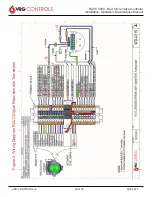
Страница 20: ...VRG CONTROLS LLC 20 of 39 MAY 2021 RCVC 3000 Red Circle Valve Controller Installation Operation Maintenance Manual Figure 2 Wiring Diagram RCVC Digital Potentiometer Transmitter ...
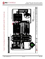
Страница 21: ...hown with Balluff BTL5 Transmitter 2 Position Feedback to RTU requires loop power 3 Digital Input 1 and 2 are Setup for 24 VDC Remote Override Enable Remote Command and Remote Override in System Inputs BTL5 B 14 GA WIRE REV DESCRIPTION DATE BY A FIRST RELEASE 2 9 2019 VI B ADDED to DI1 DI2 ADDED 24VDC CLOSE to DI1 24VDC OPEN to DI2 12 4 2019 VI D C B A A B C D 1 2 3 4 5 6 7 8 8 7 6 5 4 3 2 1 WD 02...
Страница 22: ...OCK ON THE VALVE VRG Red Circle Controller Incoming Fuse 2 AMPS NOTES Shown with Balluff BTL7 Transmitter 1 Position Feedback to RTU requires loop power 2 B REV DESCRIPTION DATE BY A FIRST RELEASE 11 19 2018 VI B ADDED to DI1 DI2 ADDED 24VDC CLOSE to DI1 24VDC OPEN to DI2 12 4 2019 VI D C B A A B C D 1 2 3 4 5 6 7 8 8 7 6 5 4 3 2 1 WD 0220 RCVC 2000 3000 FOR REMOTE RCVC Digital TRM Analog Input 12...
Страница 23: ... BLOCK ON THE VALVE VRG Red Circle Controller Incoming Fuse 2 AMPS NOTES 1 Shown with Balluff BTL7 Transmitter 2 Position Feedback to RTU requires loop power B A REV DESCRIPTION DATE BY A FIRST RELEASE 9 6 2017 VI B ADDED to DI1 DI2 ADDED 24VDC CLOSE to DI1 24VDC OPEN to DI2 12 4 2019 VI D C B A A B C D 1 2 3 4 5 6 7 8 8 7 6 5 4 3 2 1 WD 0225 RCVC 2000 3000 FOR REMOTE RCVC Digital TRM Analog Input...
Страница 24: ...K ON THE VALVE VRG Red Circle Controller Incoming Fuse 2 AMPS NOTES 1 Shown with Balluff BTL5 Transmitter 2 Position Feedback to RTU requires loop power BTL5 B REV DESCRIPTION DATE BY A FIRST RELEASE 02 09 2019 VI B ADDED to DI1 DI2 ADDED 24VDC CLOSE to DI1 24VDC OPEN to DI2 12 5 2019 VI D C B A A B C D 1 2 3 4 5 6 7 8 8 7 6 5 4 3 2 1 WD 0226 RCVC 2000 3000 FOR REMOTE RCVC Digital TRM BTL5 Analog ...
Страница 25: ...VRG CONTROLS LLC 25 of 39 MAY 2021 RCVC 3000 Red Circle Valve Controller Installation Operation Maintenance Manual ...
Страница 26: ...VRG CONTROLS LLC 26 of 39 MAY 2021 RCVC 3000 Red Circle Valve Controller Installation Operation Maintenance Manual ...
Страница 27: ...VRG CONTROLS LLC 27 of 39 MAY 2021 RCVC 3000 Red Circle Valve Controller Installation Operation Maintenance Manual ...
Страница 28: ...VRG CONTROLS LLC 28 of 39 MAY 2021 RCVC 3000 Red Circle Valve Controller Installation Operation Maintenance Manual ...
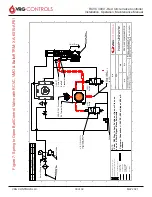
Страница 29: ...VRG CONTROLS LLC 29 of 39 MAY 2021 RCVC 3000 Red Circle Valve Controller Installation Operation Maintenance Manual ...
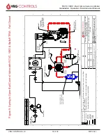
Страница 30: ...B D C B A A B C D 1 2 3 4 5 6 7 8 8 7 6 5 4 3 2 1 THE INFORMATION CONTAINED IN THISDRAWING IS THE SOLE PROPERTY OF VRG CONTROLS LLC ANY REPRODUCTION IN PART OR AS A WHOLEWITHOUT THE WRITTEN PERMISSION OFVRG CONTROLS LLC IS PROHIBITED PROPRIETARY AND CONFIDENTIAL DRAWN REVISED ENG APPR TITLE SIZE B DWG NO REV AFB 12 3 2020 VR CODE XA 6015 AP01 C NOTE COSTOMER JOB PO RCVC ASCO VMO BLF FOB 1 4 NPT FU...
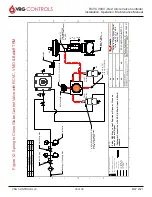
Страница 31: ... 1 THE INFORMATION CONTAINED IN THISDRAWING IS THE SOLE PROPERTY OF VRG CONTROLS LLC ANY REPRODUCTION IN PART OR AS A WHOLEWITHOUT THE WRITTEN PERMISSION OF VRG CONTROLS LLC IS PROHIBITED PROPRIETARY AND CONFIDENTIAL DRAWN REVISED ENG APPR TITLE SIZE B DWG NO REV VR CODE XA 6018 AP01 NOTE CUSTOMER JOB PO RCVC ASCOEV8327NC ASCOEV8327NO VMO BLF FOB 1 4 NPT FULL PORT BALL VALVE 1 4 NPT INSTRUMENT BAL...
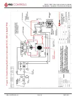
Страница 32: ...5 4 3 2 1 THE INFORMATION CONTAINED IN THISDRAWING IS THE SOLE PROPERTY OF VRG CONTROLS LLC ANY REPRODUCTION IN PART OR AS A WHOLEWITHOUT THE WRITTEN PERMISSION OF VRG CONTROLS LLC IS PROHIBITED PROPRIETARY AND CONFIDENTIAL DRAWN REVISED ENG APPR TITLE SIZE B DWG NO REV VR CODE XA 6028 AP01 NOTE CUSTOMER JOB PO RCVC ASCOEV8327NO ASCO8327NC VMO BLF FCB 1 4 NPT FULL PORT BALL VALVE 1 4 NPT INSTRUMEN...
Страница 33: ...FB D C B A A B C D 1 2 3 4 5 6 7 8 8 7 6 5 4 3 2 1 THE INFORMATION CONTAINED IN THISDRAWING IS THE SOLE PROPERTY OF VRG CONTROLS LLC ANY REPRODUCTION IN PART OR AS A WHOLEWITHOUT THE WRITTEN PERMISSION OFVRG CONTROLS LLC IS PROHIBITED PROPRIETARY AND CONFIDENTIAL DRAWN REVISED ENG APPR TITLE SIZE B DWG NO REV 12 04 2020 CODE XA 6035 AP01 B NOTE COSTOMER JOB PO RCVC ASCO VMO BLF FOG 1 4 NPT FULL PO...
Страница 34: ...VRG CONTROLS LLC 34 of 39 MAY 2021 RCVC 3000 Red Circle Valve Controller Installation Operation Maintenance Manual Figure 11 Spring to Close Globe Control Valve with RCVC Balluff TRM ...
Страница 35: ...AFB D C B A A B C D 1 2 3 4 5 6 7 8 8 7 6 5 4 3 2 1 THE INFORMATION CONTAINED IN THISDRAWING IS THE SOLE PROPERTY OF VRG CONTROLS LLC ANY REPRODUCTION IN PART OR AS A WHOLEWITHOUT THE WRITTEN PERMISSION OFVRG CONTROLS LLC IS PROHIBITED PROPRIETARY AND CONFIDENTIAL DRAWN REVISED ENG APPR TITLE SIZE B DWG NO REV 12 04 2020 CODE XA 6045 AP01 B NOTE COSTOMER JOB PO RCVC ASCO VMO BLF FCG 1 4 NPT FULL P...
Страница 36: ...VRG CONTROLS LLC 36 of 39 MAY 2021 RCVC 3000 Red Circle Valve Controller Installation Operation Maintenance Manual Figure 13 Double Acting Ball Control Valve with RCVC VMO Balluff TRM ...
Страница 37: ...VRG CONTROLS LLC 37 of 39 MAY 2021 RCVC 3000 Red Circle Valve Controller Installation Operation Maintenance Manual Figure 14 Double Acting Ball Control Valve with RCVC VMO Balluff TRM Up to 250psig ...
Страница 38: ...G CONTROLS LLC 38 of 39 MAY 2021 RCVC 3000 Red Circle Valve Controller Installation Operation Maintenance Manual Figure 15 Spring to Open Ball Control Valve with RCVC VMO Balluff TRM and Pressure Override ...
Страница 39: ...ee satisfactory results from reliance upon such information Nothing contained herein is to be construed as a warranty or guarantee expressed or implied regarding the performance merchantability fitness or any other matter with respect to the products nor as a recommendation to use any product of process in conflict with any patent VRG Controls LLC reserves the right without notice to alter or impr...