background image

V O R S I S   H D   P 3   G U I

page  2 – 33

HD P3 / Aug 2006

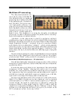
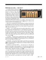
Multiband Limiter - “Airchain”

No bones about it, and no pre-

tence:  this processing section’s sole
reason for being is to make things
LOUD.  As with the three-band
compressor, it was felt that ulti-
mately the user is better served by
having all the “handles” on the pro-
cessing available.  There are a dif-
ferent set of controls for this Multi-
band Limiter, although the two truly
important ones operationally remain
similar to the “Production” style processor: “Drive” which adjusts overall
depth of limiting and gain-reduction, and “Output Level” which sets the
overall output from the multiband stage.

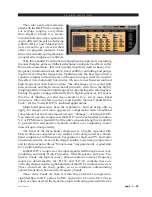
These two, assuming that initial operation is going to be from an

existing preset, are the only ones of concern, at least until confidence has
risen and the control screen no longer seems as intimidating as Concorde’s
flight deck. The specific controls for the three bands are ranged horizon-
tally across the GUI screen:

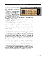
DRIVE — Yes, Virginia, there are four controls called “Drive” on the

GUI. The top one is the important one - it is the master drive for the whole
three-band section. The three below it are for the high-frequency, mid-
frequency, and low-frequency processing bands. These allow the relative
amounts of signal drive into each band to be varied;  the range is +8dB to
-20dB, more than enough to (over) emphasize a band, or effectively
remove it. In practice these should rarely be more than a very few dB adrift
of the nominal 0dB.

ATTACK — The period of time an applied signal within the band must

instantaneously exceed the threshold in order to reduce the output signal
down to the threshold. 0.5mS is recommended for zero-overshoot limit-
ing. Free-form range is 0.2mS to 1Sec.

RELEASE — The time the band’s limiter’s gain takes to recover from

a typical degree of limiting once the signal no longer exceeds the threshold.
50mS is recommended for transparent zero-overshoot limiting. Overall
range is 33mS to 1Sec.

BACKOFF (CLIP BACKOFF) — The discussion on “Backoff” as

applied to the Output Limiter (on page 3-17) is hereby set as homework.
Review is strongly recommended since it is directly appropriate to the
limiters used in this section. For the recommended zero-overshoot / zero-
attack settings, “Backoff” should be set at 0dB.

In short, “Backoff” is the amount that the limiter’s threshold is reduced

below it’s downstream zero-attack-time “clipper” threshold. It becomes
relevant if the attack time is made greater than approximately 2mS. Slower
attack times allow greater peaks to ‘escape’ through a limiter;  reducing its
threshold with “Backoff” can prevent too much signal being clipped,
which could potentially sound unpleasant. The range is 0dB to -10dB.

Содержание HD P3

Страница 1: ...TECHNICAL MANUAL 600 Industrial Drive New Bern North Carolina USA 28562 MULTIBAND SIGNAL PROCESSOR HD P3 DIGITAL ORSIS...

Страница 2: ...l Multiband Signal Processor Technical Manual HD P3 Digital Multiband Signal Processor Technical Manual HD P3 Digital Multiband Signal Processor Technical Manual HD P3 Digital Multiband Signal Process...

Страница 3: ...In a domestic environment this This is a Class A product In a domestic environment this This is a Class A product In a domestic environment this This is a Class A product In a domestic environment th...

Страница 4: ...SPDIF 1 7 XLR Inputs Outputs Pinout Drawing 1 8 DB 25 Inputs Outputs RJ 45 Ethernet DB 9 GPI Pinout Drawing 1 9 Chapter 2 Vorsis HD P3 GUI Getting Started 2 3 Connecting the HD P3 and the GUI 2 3 IP...

Страница 5: ...24 HD P3 Features for AM Broadcast 2 25 Brick wall Bandwidth 2 25 Emphasis 2 25 Asymmetric Output Peak Limiter 2 26 Mono 2 26 Parametric Equalizer 2 26 Multiband Processing 2 27 Multi Band AGC Compres...

Страница 6: ...S Chapter 3 Schematic and Load Sheet Drawings HD P3 Processor Main Card Schematic 3 2 Load Sheet 3 5 HD P3 Processor VU Card Schematic 3 6 Load Sheet 3 7 Appendices Appendix 1 Parameters Units and Ran...

Страница 7: ...s 1 3 Inputs 1 3 Outputs 1 4 General Purpose Interface 1 5 Ethernet Interface 1 5 Typical Ethernet Cable 1 5 Typical Crossover Cable 1 6 Digital Audio Connections 1 6 Unbalanced Analog Connections 1 6...

Страница 8: ...be stored and replayed as password protected presets The front panel display includes input output and gain reduction meters Remote monitoring and operational control is possible using Ethernet enabl...

Страница 9: ...r line level analog audio input nominal 4dBu balanced connections The analog line inputs exhibit a bridging impedance and can handle signals up to 20dBu A third female XLR connector is available to ha...

Страница 10: ...al outputs are available also on the DB 25 connector ANALOG OUT XLR M Pin 1 XLR1 SH LINE 1 OUT SH Pin 2 XLR1 HI LINE 1 OUT HI Pin 3 XLR1 LO LINE 1 OUT LO Pin 1 XLR2 SH LINE 2 OUT SH Pin 2 XLR2 HI LINE...

Страница 11: ...n 5 GPI 8 IN Ethernet Interface 100Mbps Connect your HD P3 to your local Ethernet network using a straight pin to pin CAT5 cable The default IP address and subnet is 192 168 1 191 255 255 255 0 Please...

Страница 12: ...facturer s recommendations for termination instructions Unbalanced Analog Connections ANALOG INPUTS Wire to the processor input end with typical shielded two conductor cable like Belden 9451 just as i...

Страница 13: ...CA style connector Note that the SPDIF signal level of approximately 500mV and 75 ohm impedance does not correctly match the processor s AES 3 input We highly recommend using a balun or format convert...

Страница 14: ...1 XLR SH AES IN SH PIN 2 XLR HI AES IN HI PIN 3 XLR LO AES IN LO XLR F 1 2 3 Analog Out XLR M PIN 1 XLR SH LINE 1 OUT SH PIN 2 XLR HI LINE 1 OUT HI PIN 3 XLR LO LINE 1 OUT LO XLR1 M PIN 1 XLR SH LINE...

Страница 15: ...GROUND LINE 1 IN LO LINE 2 IN SH LINE 2 IN HI N C LINE 1 OUT SH LINE 1 OUT HI LINE 2 OUT LO AES IN SH AES IN HI AES 1 OUT LO AES 2 OUT SH AES 2 OUT HI 5 4 3 2 1 17 16 15 14 8 7 6 20 19 18 10 9 23 22 2...

Страница 16: ...quency Domain Graph 2 8 Bargraph Metering 2 9 Signal Path Selection 2 9 Control Area Region 2 10 Input 2 11 Signal Path Routing 2 12 Symmetry 2 12 Phase 2 12 Filter 2 13 High Pass Filter 2 13 Notch 2...

Страница 17: ...tion 2 27 Transparent Compression 2 30 Compressing for Effect 2 30 AGC 2 31 Multiband Limiter Airchain 2 33 Loud 2 35 Creating a sound 2 36 Deep Gain Reduction 2 36 Setting Up the Output 2 37 System 2...

Страница 18: ...and the GUI The HD P3 and PC running the HD P3 s GUI program can be straightforwardly connected together over a standard Ethernet Local Area Network LAN The HD P3 should be installed powered up and ve...

Страница 19: ...t IP address Make sure both your PC and HD P3 areconnectedtothesamephysicalnetwork oruseacrossovercableforadirect peer to peer connection between a PC and the HD P3 For instant verification via the GU...

Страница 20: ...audio meters will also begin moving if you have audio playing and are actually Online You may now Close the IP Assignment dialog box That s it Troubleshooting IP Addressing Problems Once you have chan...

Страница 21: ...it out of the way of the busiest DHCP addressing However it is always wise to check with your local friendly network administrator If the network warrants it the Subnet and Gateway values may need to...

Страница 22: ...Itothe required position In true Windows fashion the GUI may be minimized taken off the screen and closed by way of the familiar controls at the extreme top right Description of the features and funct...

Страница 23: ...ncy response filter responses de esser sidechain filter response etc The de esser s dynamic frequency response shows here too as a dynamic upside down shark fin when in operation INPUT AFast FourierTr...

Страница 24: ...ght of Graph left limiter gain reduction right limiter gain reduction left output signal level right output signal level The level meters are dual indicating peak over average with peaks riding as a l...

Страница 25: ...ed made finer byholdingdownthekeyboard s control key Ctrl while adjusting the control as above Left to rightacrosstheupperpor tion of this area are a series of buttons corresponding to individual or l...

Страница 26: ...id applied AES EBU input signal Virtual LED s in the lower right corner of the HD P3 GUI indicate the status of the external sample rate present at the AES input connector The VALID LED will go out If...

Страница 27: ...the fundamental and harmonic elements of a voice far less painful than it seems the relatively high asymmetry positive going signal peaks vs negative going peaks of some 8 to 10dB of a normal voice c...

Страница 28: ...ect to heavy compression A common usage in live sound is to effectively turn a microphone off when not being talked sung into so as to reduce corruption of a mix or reduce the chances of feedback with...

Страница 29: ...mes the gain reduction is required to be subtle so as not to draw attention to the fact that the expander is in operation under these conditions shallow expansion ratios such as 1 1 5 or 1 2 are prefe...

Страница 30: ...ld FREQUENCY This is the center frequency of a filter which determines the band of frequencies over which the de esser operates It is operated in conjunction with BANDWIDTH which determines how wide o...

Страница 31: ...unding while not interfering with the important voice frequencies It should be noted that the de esser is quite sensitive to changes in input level ensure that the input signal is at a reasonable leve...

Страница 32: ...within that link the excellent zero overshoot output peak limiter in the HD P3 captures any overshoots that may spring from the pre emphasis Using the pre emphasis from the Output section allows the m...

Страница 33: ...sounding console output So in short The pre emphasis is to emulate that required of a typical transmission scheme By bringing it into the HD P3 superior control over theoverallsignalpath andsuperiora...

Страница 34: ...he M S switch will present a mono sum of the applied left and right signals from a stereo production or air suite into the Left or A path of the HD P3 The Right or B path would be ignored in this case...

Страница 35: ...es Beatles in particular and having instruments panned hard the producers didn t get the message were trying to be artsy or it just naturally isn t like that jazz classical In the kind of world the HD...

Страница 36: ...eed ATTACK Theperiodoftimeanappliedsignalmustinstantaneously exceed the Threshold in order to reduce the output signal down to the threshold 0 5mS is recommended for zero overshoot limiting RELEASE Th...

Страница 37: ...r limiter attacktimeswhilstretainingtheabsolutemaximumoutputlimitsetbytheClip In general it is set by ear like many other settings the degree of clipping which is tolerable is truly subjective no amou...

Страница 38: ...captured and controlled regardless of the look ahead technique The longer the attack time the more energy escapes the limiter at not very great extremes a clipper by definition zero attack time allows...

Страница 39: ...of delay applied to the AES 2 output The slider s range is either OFF or adjustable from 6 0 to 49 9 milliseconds of delay in 100 microsecond increments DELAY UNPROCESSED checking this box routes the...

Страница 40: ...quency emphasis to combat the inevitable high frequency rolloff of the IF filters in AM receivers The NRSC standard for use in conjunction with the above 10kHz brick wall filter is for use of a modifi...

Страница 41: ...90 of 130 or 117 For a typical real world depth of 95 negative modula tion the Positive Modulation control would need to be set at 131 to achieve actual 125 sender positive modulation Confused yet Pos...

Страница 42: ...iffering types of program material Thechoicebetweenthesetwostylesofmultibandprocessorismadeby check boxes on the Multiband screen of the GUI and as a ProcMode selection under Multi on the unit itself...

Страница 43: ...or the buck for the Vorsis HD P3 s intended applications Multi band processors have the reputation born of being able to apply far deeper and more aggressive compression than broadband compressors for...

Страница 44: ...bands Threshold controls are in the same vertical line as Drive and that the three bands Trim controls are in line under Makeup In the HD P3 the three traditional Threshold controls may be regarded as...

Страница 45: ...source material It won t take much a few dB here or there across the three Forpre recordedmusic asubtle sweetening effectmaybeintroduced by reducing the mid Trim just a few dB and adjusting the crosso...

Страница 46: ...10kHz can lend a real sweetness to the extreme highs but at the expense of potential loudness to be gained by sharing the mid frequency compressor s load Be aware of over compressing the high frequen...

Страница 47: ...and character of the program material the AGC can follow the average long term level changes and create a gain reduction bed some 12dB to 6dB under the compression gain reduction peaks The AGC rides t...

Страница 48: ...ive amounts of signal drive into each band to be varied the range is 8dB to 20dB more than enough to over emphasize a band or effectively remove it In practice these should rarely be more than a very...

Страница 49: ...lease and AGC In These control the operation and time constants for a three band AGC system which when selected underlies the operation of the three bands limiters The time constants are common to all...

Страница 50: ...ion dropping below the threshold set by the Freeze control for more than 1 4 second it applies a v e r y l o n g time constant to the AGC approx 30 seconds This prevents the gain suddenly rising preci...

Страница 51: ...de here an effort should be made to keep the average of the trims settings around 0dB with overall lift and cut being done by the Output Level control By the time the signal has passed through the mul...

Страница 52: ...trims and possibly post EQ it is necessary to match the multiband limiter s output with the rest of the world It is presumed that a desired output level from the box has been decided and that the Out...

Страница 53: ...Used primarily when the input mode choice is Dual Mono though some presets utilizing M S processing utilize the split SECURITY Allows access unto password world Passwords button It is presumed that a...

Страница 54: ...n until deliberately closed allowing differing presets to be double clicked upon readily in succession This is a very direct means of comparing presets It is important to remember to save the present...

Страница 55: ...and the HD P3 and its mirror archive in the GUI Devices A list of HD P3 devices with which the GUI has had causetobecomefamiliarisshownina Windows box Highlighting the desired HD P3 s name and hittin...

Страница 56: ...gain access to respective management screens Accessing Menu Options Right clicking anywhere on the Vorsis HD P3 Control Panel will open a pop up menu tree with access to File Hardware and Presets cho...

Страница 57: ...licking on the name brings up a Differences parameter by parameter setting by setting comparison list between the HD P3 and the GUI mirror archive SYNCH allows the presets within the HD P3 and the GUI...

Страница 58: ...de without affecting signal processing within the HD P3 itself which can continue to be processing away obliviously Preset list manipulation can be undertaken Online too but only by those with nerves...

Страница 59: ...lays the current software versions running on your HD P3 Software Update opens the Choose file to download dialog box Only files of type vbn are visible Assign IP Address opens a dialog box that allow...

Страница 60: ...HD P3 Aug 2006 S C H E M A T I C D R A W I N G S I O Schematic Drawings Load Sheets Chapter Contents HD P3 Processor Main Card Schematic 3 2 Load Sheet 3 5 HD P3 Processor VU Card Schematic 3 6 Load S...

Страница 61: ...N VIN VIN VIN VIN PH PH PH PH PH PH PH PH PH BOOT PGND PGND PGND PGND GND 0 1uF C398 0 1uF C403 0 1uF C391 0 1uF C396 TP12 TP13 R285 220 GND GND GND 0 01uF C399 0 01uF C392 0 01uF C401 3900pF C402 0 0...

Страница 62: ...___ ______ _ ____ GND GND 3 3V 3 3V L12 U6 5 4 3 2 1 10 11 12 13 14 15 16 17 9 7 22 8 18 19 20 25 24 28 27 26 21 23 6 CS8416 ____ TX C U RCBL 96KHZ AUDIO NV RERR TXSEL0 TXSEL1 RXSEL0 RXSEL1 OLRCK OSCL...

Страница 63: ...2 1 8 4 U25 33pF C113 R164 2 43K C100 33pF AGND 2dBu AGND 5532 7 6 5 U25 33pF C114 R154 2 43K C101 33pF AGND 2dBu R163 10 0K R152 10 0K R166 10 0K R155 10 0K R165 2 43K R153 2 43K AGND AGND C102 3900p...

Страница 64: ...page 3 5 HD P3 Processor Main Card Load Sheet HD P3 Oct 2007...

Страница 65: ...ellow Red Red Red Red Red Red Green Green Green Green Green Green Green Green Green Green Green Green Green Green Green Green Green Green Green Green Orange Yellow Yellow Yellow Yellow Red Red Red Red...

Страница 66: ...page 3 7 HD P3 Processor VU Card Load Sheet HD P3 Aug 2006...

Страница 67: ...page A 1 HD P3 Aug 2006 A P P E N D I C E S Appendix 1 Parameters Units and Ranges A 3 Appendix 2 Replacement Parts List A 8 Appendices...

Страница 68: ...page A 2 HD P3 Aug 2006 A P P E N D I C E S Appendix 1 Contents Parameters Units and Ranges A 3...

Страница 69: ...S digital 4dBu analog Input Gain a Analogue Line Input Type Electronic Differential Input Impedance 10kohm bridging Optimum Source Impedance 1kohm b Digital Line Input Type AES3 EBU Maximum Gain 12dB...

Страница 70: ...1 oct 6dB 2 800Hz 0 5 oct 4dB 3 2 8kHz 0 66 oct 3dB 4 16kHz 0 4 oct 8dB De Esser Recursive style true not broadband De Esser Threshold 10 to 60dBfs 20dBfs Attack 0 1mS 100mS 5mS Release 50mS 500mS 100...

Страница 71: ...33mS 1Sec 150mS Ratio soft knee 1 1 20 1 LF Crossover Frequency 20Hz 1kHz 250Hz HF Crossover Frequency 1kHz 20kHz 4kHz Drive Overall Threshold 0 100 50 Trim HF MF LF 18dB 0dB Makeup Gain 20 to 48dB 0d...

Страница 72: ...L R Pre and De emphasis Pre emphasis 50 or 75uS available at input Pre emphasis or De emphasis 50 or 75uS available at output Defaults Off AM Bandwidth Filter Available at output 4 5kHz Europe 5kHz US...

Страница 73: ...ser replaceable parts in the Vorsis HD P3 A complete list of available components is shown on the next page Contact Vorsis technical support for further information Vorsis 600 Industrial Drive New Ber...

Страница 74: ...AT RIBBON CABLE 150007 POWER CORD 7 1 2 BLACK POWER CORD 150017 RIBBON PLUG 40 PIN RIBBON PLUG 250053 I O CONNECTOR DB 9 RIGHT ANGLE PC MOUNT CONNECTOR 220016 I O CONNECTOR RIGHT ANGLE 25 PIN PC MOUNT...

Отзывы: