


600 Industrial Drive
New Bern, NC 28562
VCC
POLYSW
0.16A
F2
VCC
POLYSW
0.16A
F1
SS14 D2
SS14 D1
AGND
AGND
AGND
AGND
CT2
1
2
3
4
5
6
7
8
9
RXD+
TXD+
RXD-
TXD-
B3
B1
B2
B4
B5
B6
B7
B8
CT8
CT1
1
2
3
4
5
6
7
8
9
10
11
12
13
14
15
16
17
18
19
20
21
22
23
24
25
CT24
1
2
3
4
5
6
7
8
9
10
11
12
13
14
15
16
17
18
19
20
21
22
23
24
25
26
27
28
29
30
31
32
33
34
35
36
37
38
39
40
CT23
1
2
3
4
5
6
7
8
9
10
11
12
13
14
15
16
17
18
19
20
21
22
23
24
25
26
27
28
29
30
31
32
33
34
35
36
37
38
39
40
1
2
3
CT15
1
2
3
CT14
1
2
3
CT13
AGND
1
2
3
CT12
AGND
1
2
3
CT11
1
2
3
CT10
AGND
3
2
1
CT9
A3
A8
A7
A6
A5
A4
A2
A1
CT8
A1
A2
A4
A5
A6
A7
A8
A3
CT7
B8
B7
B6
B5
B4
B2
B1
B3
CT7
8
7
6
5
4
3
2
1
CT5
1
2
3
4
5
6
7
8
CT4
AES IN HI
AES IN LO
AES 1 OUT HI
AES 1 OUT LO
AES 2 OUT HI
AES 2 OUT LO
R329 10.0K
CT25
1
2
3
4
5
6
7
8
9
CT22
1
2
3
4
5
6
7
8
9
10
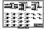
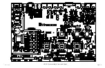
HD P3 / Oct 2007
1 OF 8
5-17-07
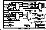
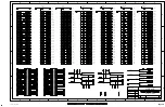
MAP-1D PCB
80S0048-1
MAP-1
W# 700817
D
page 3 - 2
B
C
A
D
B
C
A
D
APPROVALS
D
DWG. NO.
FSCM NO.
ISSUED
CHECKED
DRAWN
SHEET
SCALE
CONTRACT NO.
REV
SIZE
DATE
- SA UR US - Sergey Averin -
SA
SA
SA
5
4
6
3
7
2
8
1
5
4
6
3
7
2
8
1
GND
GND
GND
GND
VCC
R344
10.0K
VCC
R338
88.7K
GND
0.1uF
C397
GND
GND
L21
GND
GND
R342 100
R341 10.0K
0.01uF
C400
R339
11.0K
GND
R340
88.7K
GND
R343
2.00K
GND
GND
GND
GND
VCC
R336
10.0K
VCC
R330
88.7K
GND
0.1uF
C390
GND
GND
L20
GND
GND
R333 10.0K
0.01uF
C393
R331
40.2K
GND
R332
100K
GND
+1.2V
+1.8V
TPS54610
U42
28
27
26
25
24
23
22
21
20
19
18
17
16
15
14
13
12
11
10
9
8
7
6
5
4
3
2
1
PGND
POWERPAD
RT
SYNC
SS/ENA
VBIAS
PWRGD
COMP
VSENSE
AGND
VIN
VIN
VIN
VIN
VIN
PH
PH
PH
PH
PH
PH
PH
PH
PH
BOOT
PGND
PGND
PGND
PGND
GND
TPS54610
U41
28
27
26
25
24
23
22
21
20
19
18
17
16
15
14
13
12
11
10
9
8
7
6
5
4
3
2
1
PGND
POWERPAD
RT
SYNC
SS/ENA
VBIAS
PWRGD
COMP
VSENSE
AGND
VIN
VIN
VIN
VIN
VIN
PH
PH
PH
PH
PH
PH
PH
PH
PH
BOOT
PGND
PGND
PGND
PGND
GND
0.1uF
C398
0.1uF
C403
0.1uF
C391
0.1uF
C396
TP12
TP13
R285 220
GND
GND
GND
0.01uF
C399
0.01uF
C392
0.01uF
C401
3900pF
C402
0.01uF
C394
3900pF
C395
R335
2.00K
R334 100
47uF
C374
47uF
C365
47uF
C371
47uF
C362
R337 10.0K
GND
47uF
C364
GND
47uF
C361
47uF
C363
47uF
C366
47uF
C370
47uF
C373
1uF
C375
GND
1uF
C372
GND
TP15
GND
TP14
GND
GND
VCC
LT1117
Q4
2
1
3
GND
IN OUT
C218
4.7uF
C195
4.7uF
+2.5V
TP6
TP5
GND
+1.8V
+3.3V
C326
1uF
3
2
1
LT1117
Q5
ADJ
IN OUT
R283
68
R276
150
1uF
C356
C354
1uF
MICLINE1INHI
MICLINE1INLO
MICLINE2INHI
MICLINE2INLO
AESINHI
AESINLO
LINE1OUTHI
LINE1OUTLO
LINE2OUTHI
LINE2OUTLO
AESOUT1HI
AESOUT1LO
ETH_P3
ETH_P5
ETH_P7
ETH_P1
ETH_P4
ETH_P6
ETH_P8
ETH_P2
GPI2IN
GPI8IN
GPI5IN
GPI_COM
GPI1IN
GPI3IN
GPI4IN
GPI6IN
GPI7IN
GND
MC1+5V
AGND
AGND
LINE2OUTLO
LINE1OUTHI
AGND
MICLINE2INHI
AGND
MICLINE1INLO
AGND
LINE2OUTHI
AGND
LINE1OUTLO
AGND
MICLINE2INLO
MICLINE1INHI
AGND
AGND
GND
MC2+5V
MC1+5V
MC2+5V
MC15V
MC25V
+3.3V
+3.3V
SW_Y_2
SW_Y_3
SW_Y_4
SW_Y_5
SW_Y_1
GND
GND
GND
GND
+3.3V
+3.3V
VCC
VCC
+3.3V
+3.3V
GND
GND
GND
GND
+3.3V
+3.3V
VCC
VCC
SW_Y_6
SW_Y_7
SW_Y_8
SW_Y_9
SW_Y_A
SW_Y_B
SW_1_X
SW_2_X
SW_3_X
DSPL_CLK
DSPL_DIN
DSPL_RS
GND
GND
GND
AESOUT2HI
AESOUT2LO
AESINHI
AESINLO
AESOUT1HI
AESOUT1LO
AESOUT2HI
AESOUT2LO
AESINLO
AESINHI
AESOUT2LO
AESOUT2HI
AESOUT1LO
AESOUT1HI
+2.5V
DB9_TX
GND
DB9_RX
DB9_TX
DB9_RX
GND
REG_SYNC
PWRGD18
REG_SYNC
+3.3V
PWRGD12
INSTALL ONE
NOT INSTALLED
DSP56367
+1.8V
DSP56367
TMS320C6713BPYP
XC3S200
XC3S200
AES 1 OUT RJ-45 CONNECTOR
LO
HI
AES 2 OUT
MIC2 CONTROL RJ-45 CONNECTOR
MIC1 CONTROL RJ-45 CONNECTOR
MIC/LINE "1" IN
MIC/LINE "2" IN
AES IN
LO
HI
LO
HI
LO
HI
LINE "1" OUT
LINE "2" OUT
AES 1 OUT
LO
HI
HI
LO
HI
LO
ETHERNET RJ-45 CONNECTOR
AES IN RJ-45 CONNECTOR
DB-9 CONNECTOR
GPI
DB-25 CONNECTOR
-50dBu (+4dBu) BAL
-50dBu (+4dBu) BAL
+4dBu BAL
+4dBu BAL
+2.5V
AES 2 OUT RJ-45 CONNECTOR
DEBUG RS-232
DB-9 CONNECTOR
10 PIN
CONNECTOR
DEBUG RS-232


