


6
1.1 PRINCIPLE COMPONENTS
•
A fully integrated electronic control board featuring electronic
temperature control, anti-cycle control, pump over-run, self-
diagnostic fault indicator, full air/gas modulation
•
Aluminium heat exchanger
•
Electronic ignition with flame supervision
•
Integral high-head pump
•
Fan
•
Expansion vessel
•
Water pressure switch
•
Flue sensor
•
Pressure gauge
•
Safety valve
1.2 MODE OF OPERATION (at rest)
When the appliance is at rest and there are no requests for
heating or hot water, the following functions are active:
•
frost-protection system – the frost-protection system protects
the appliance against the risk of frost damage. For CH line, if
the main temperature falls to 5°C, the appliance will function
on minimum power until the temperature on main reaches
35°C.
•
anti-block function – the anti-block function enables the pump
to be energised for short periods, when the appliance has
been inactive for more than 24-hours.
1.3 MODE OF OPERATION (Heating)
When there is a request for heat via the time clock and/or any
external control, the pump and fan are started, the fan speed
will modulate until the correct signal voltage is received at the
control PCB. At this point an ignition sequence is enabled.
Ignition is sensed by the electronic circuit to ensure flame stability
at the burner. Once successful ignition has been achieved, the
electronic circuitry increases the gas rate to 75% for a period of
15 minutes. Thereafter, the boiler’s output will either be increase
to maximum or modulate to suit the set requirement. When
the appliance reaches the desired temperature the burner will
shut down and the boiler will perform a three-minute anti-cycle
(timer delay).
When the request for heat has been satisfied the appliance
pump and fan may continue to operate to dissipate any residual
heat within the appliance.
1.4 SAFETY DEVICES
When the appliance is in use, safe operation is ensured by:
•
a water pressure switch that monitors system water pressure
and will de-activate the pump, fan, and burner should the
system water pressure drop below the rated tolerance;
•
fan speed sensor to ensure safe operation of the burner;
•
a high limit thermostat that over-rides the temperature control
circuit to prevent or interrupt the operation of the burner;
•
flame sensor that will shut down the burner when no flame
signal is detected;
•
flue sensor;
•
a safety valve which releases excess pressure from the
primary circuit.
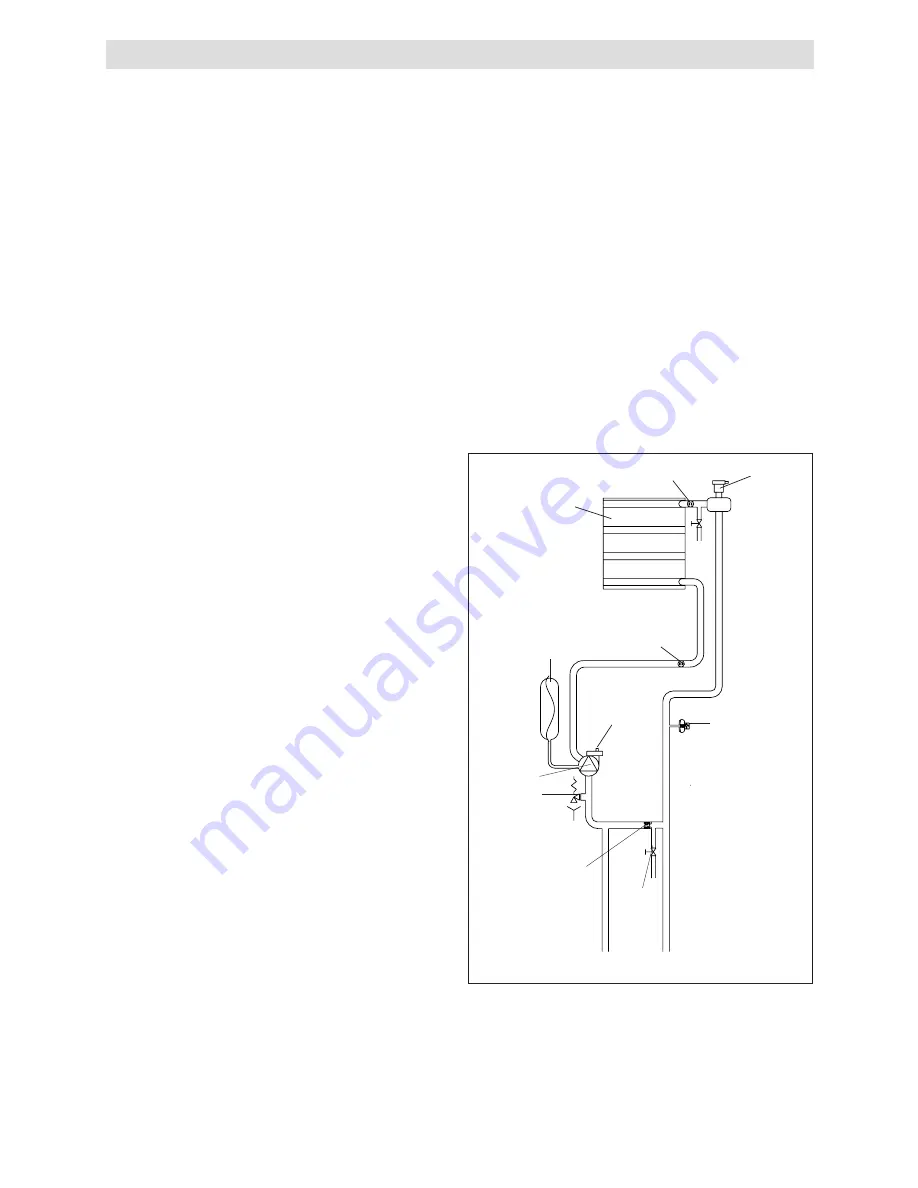
Fig. 4
Expansion
vessel
Safety
valve
Pump
Return
temperature
sensor
Main heat
exchanger
Bottom
AAV
Pressure
switch
Drain
valve
Flow temperature
sensor
Top AAV
Automatic
by-pass
CH
return
CH
flow
SECTION 1 - DESIGN PRINCIPLES AND OPERATING SEQUENCE


