


26
NOTE
Always check and/or adjust the minimum and
maximum gas pressures whilst the appliance is
heating the radiators and HW cylinder.
7.3.2
SETTING THE MIMIMUM BURNER PRESSURE
(see fig. 37)
Once the maximum burner pressure has been
checked and/or adjusted, remove one of the grey
wires from the modulating coil. Compare the
reading on the manometer with the value
described in 2.2. If adjustment is required, turn
the inner (red) crosshead screw clockwise to
increase, or counter-clockwise to decrease the
burner pressure, whilst ensuring that the outer
(10mm) nut does not move. When checking and/
or adjustment has been completed, isolate the
appliance from the electrical supply, replace the
protective cap, refit the grey wire to the
modulating coil, remove the manometer, and
tighten the outlet test nipple.
IMPORTANT, A GAS SOUNDNESS CHECK
MUST BE CARRIED OUT.
7.4
COMBUSTION ANALYSIS TEST
A combustion analysis check can easily be
carried out on the appliance via the test points
located on the top of the appliance, however you
must check that the burner pressures are set
correctly (see 7.3).
●
Insert the flue gas analyser probe into the right
hand test point (see fig 38).
●
Locate and remove the protective cap that
conceals the ‘CO mode’ button (see fig. 38).
●
Light the boiler as described in 5.6 and press
the ‘CO mode’ button once.
●
The boiler will now enter the combustion
analysis mode (CO mode) for a period of 15
minutes. During this time it will remain on full
gas and ‘CO’ will be displayed on the LED
display.
●
Once the flue gas analysis has been made,
press the ‘CO mode’ to resume normal
operation.
7.5
CHECKING THE EXPANSION VESSEL
Carry out the component removal procedure as
described in 6.4. You must ensure that the boiler
is completely drained of water.
Using a suitable pressure gauge, remove dust
cap on expansion vessel and check the charge
pressure. The correct charge pressure should be
1.0 bar
±
0.1 bar.
IIf the charge pressure is less, use a suitable
pump to increase the charge.
NOTE
You must ensure the safety valve is in the open
position whilst re-charging takes place. Replace
the dust cap and carr y out the relevant
commissioning procedure (section 5).
7.6
EXTERNAL FAULTS
Before carrying out any faultfinding or component
replacement, ensure the fault is not attributable
to any aspect of the installation.
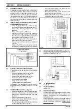
7.6.1
INSTALLATION FAULTS
Symptom
Possible causes
No ignition
Check wiring
Check electrical supply
No HW or heating
Check wiring of time clock
and/or external thermostats
Fig. 37
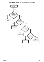
Fault code
Possible causes
01
Gas supply problem
Gas line requires purging
Reversed polarity
Broken, internal flue joint
02
Flow/return valves closed
Stuck pump
03
Debris in flue system
Debris in flue venturi
04
Insufficient water pressure
Air in boiler
Fig. 38
Protecting
cap
Air analysis outlet
Fumes analysis outlet
Содержание Synergy 29
Страница 1: ...Installation Servicing Instructions THESE INSTRUCTIONS TO BE RETAINED BY USER ...
Страница 40: ...38 Fig 45 ...


