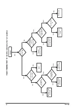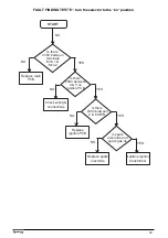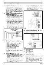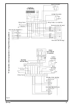
25
SECTION 7
CHECKS, ADJUSTMENTS AND FAULT FINDING
7.1
CHECKING APPLIANCE OPERATION
When carrying out any repairs or servicing to the
appliance, the relevant commissioning procedure
must be undertaken to ensure the continued safe
operation of the appliance. Particular attention
should be made to ensure gas soundness, water
soundness, and the electrical integrity of the
appliance.
7.2
APPLIANCE MODE OF OPERATION
NOTE: there must be sufficient system water
pressure (min. 0.5 bar) to ensure the water
pressure switch is activated. If there is insufficient
system pressure the pump and fan will be
prevented from operating.
7.2.1
SELECTOR SWITCH IN THE OFF POSITION
When the selector switch is in the OFF position,
there is no LED display or LED status indicator.
The appliance will not respond to any heating/
HW requests.
Active Functions:
●
frost-protection system
●
pump anti-block.
7.2.2
SELECTOR SWITCH IN THE ON POSITION
When the selector switch is in the ON position,
the status LED is illuminated and the LED display
shows the current temperature measured at the
thermistor.
Active Functions:
●
frost-protection system
●
pump anti-block
●
fan anti-block.
7.2.3
APPLIANCE FUNCTIONS
●
Frost-protection: this function is only active
when there are no requests for heating or HW.
Should the temperature of the primar y
thermistor drop below 7
°
C, the pump will be
activated for approximately 20-minutes. Should
the temperature of the primary thermistor
exceed 10
°
C during this period, the cycle will
be aborted. If the temperature drops below
4
°
C, the boiler will operate on minimum power
until the temperature of the primary thermistor
reaches 30
°
C. Thereafter the pump & fan will
over-run for 30-seconds.
●
Anti-block cycle: when there has been no
heating or HW request for 19-hours, the anti-
block cycle is activated. The pump will be
activated for a period of 1-minute if the selector
switch is in the ON position, the fan will also
be active for 1-minute.
7.2.4
HEATING/HW MODE
With the selector switch in the ON position and
any additional controls (time clock, room
thermostat, etc,) calling for heat, the appliance
will operate in the heating/HW mode. The pump
and fan will be active. The operation of the fan
causes the analogue pressure switch (PAD) to
deliver a signal voltage to the control PCB. If the
signal voltage is sufficient a slow ignition
sequence is enabled, whereby the current
supplied to the gas valve modulating coil is
progressively increased from minimum to
maximum over a period of 8-seconds. During this
period the ignition electrode sparks continuously
even if the burner has ignited.
NOTE
If the spark/sensing electrode does not sense
ignition the appliance will then go to lockout.
Ignition is sensed by the electronic circuitry to
ensure flame stability at the burner. Once
successful ignition has been achieved, the
electronic circuitry allows 75% of the full gas rate
through the appliance. After 15 minutes the gas
rate is increased to maximum (100%).
When the set-point has been reached (the
position of the temperature selector) as measured
at the primary thermistor, the appliance will begin
the modulation phase whereby the fan and gas
valve will continuously modulate to maintain the
set-point. If the temperature continues to rise and
exceeds the set-point by 6
°
C, the burner will shut
down and the boiler will perform a three-minute
anti-cycle (timer delay).
A new ignition sequence will be enabled when
the 3-minute anti-cycle has been performed and
the temperature at the primary thermistor has
dropped 6
°
C below the set-point.
NOTE
The timer delay can be de-activated by the
insertion of a ‘jumper’ on the PCB or by isolating
the appliance from the electrical supply for 30
seconds.
When the request for heating/HW has been
satisfied, the appliance pump and fan may
continue to circulate to dissipate any residual heat
within the appliance.
7.3
CHECKING AND ADJUSTING BURNER PRES-
SURE (see fig. 17)
Although the burner pressure is factory set, it is
necessary to check it during servicing or if the
gas valve has been removed.
Isolate the appliance from the electrical supply
and attach a suitable manometer to the gas valve
outlet test nipple.
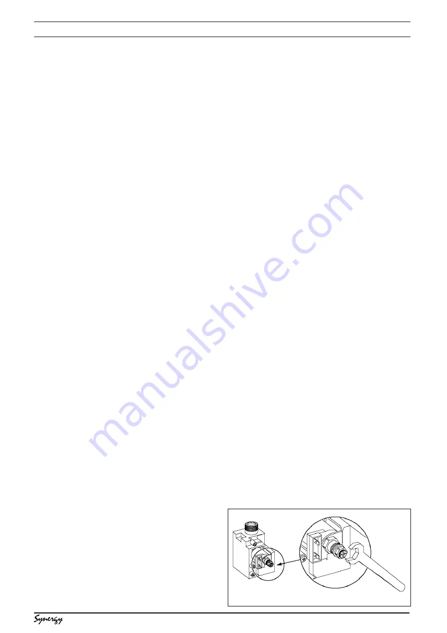
7.3.1
SETTING THE MAXIMUM BURNER PRES-
SURE (see fig. 36)
Light the boiler as described in 5.6 and compare
the reading on the manometer with the value
described in 2.3. If adjustment is required, remove
the protective cap from the gas valve modulating
coil assembly and turn the outer (10mm) nut
clockwise to increase, or counter-clockwise to
decrease the burner pressure.
Fig. 36
Содержание Synergy 29
Страница 1: ...Installation Servicing Instructions THESE INSTRUCTIONS TO BE RETAINED BY USER ...
Страница 40: ...38 Fig 45 ...


