


24
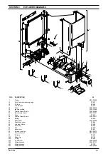
Fig. 31
Carefully unclip the wires from the air chamber
and withdraw the wiring & grommet from the air
chamber. Disconnect the electrode lead and
burner thermostat wires. Disconnect the outlet
gas pipe, the flow & return pipes and the
condense pipe from the air chamber.
Locate and remove the 2-screws that secure the
lower section of the air chamber. Locate and
remove the 2-screws that secure the upper
section of the air chamber. The complete air
chamber assembly can now be lifted clear from
the appliance. Disconnect the flexible expansion
pipe from the vessel (fig. 31). Locate and remove
the 2-screws that secure the vessel (1). The
expansion vessel can now be removed. Replace
in the reverse order. Take extreme care when
refitting the wiring to the air chamber. Ensure all
seals are in good condition, taking care to ensure
they are replaced correctly.
6.21
LATENT HEAT COLLECTOR fig’s. 32 & 33
Carry out component removal procedure as
described in 6.4. Remove the flue hood and fan
assembly as detailed in 6.16. Disconnect the
condense sensor wire from the sensor.
Fig. 32: disconnect and remove the inlet (1),
outlet (3) and condense pipes (2) from the
collector.
Fig. 33: unscrew and remove the 3 screws (1)
that secure the collector to the air chamber and
disconnect the collector (2) from the flue
connection. Replace in the reverse order ensuring
all seals are intact and located correctly.
Fig. 34
8
9
6
4
2
3
5
7
1
2
1
3
7
5
4
8
6
9
6.21A D I S M A N T L I N G T H E L AT E N T H E AT
COLLECTOR (see fig. 34)
During routine servicing or maintenance, there
is no requirement to remove or dismantle the
collector, however should it be deemed necessary
to dismantle the collector, all seals should be
discarded and replaced with new ones.
6.22
CONDENSE TRAP REMOVAL (see fig. 35)
Carry out component removal procedure as
described in 6.4. Disconnect the flexible (outlet)
condense pipe from the condense trap (1).
Disconnect the rigid (inlet) condense pipe from
the condense trap (2). Locate and remove the
pins that secure the trap to the lower frame of
the boiler (3). Carefully remove the condense trap.
Replace in the reverse order. If necessary remove
the upper connection of the pipe (4).
Fig. 32
6
4
5
6
4
3
1
2
6
6
4
5
2
1
3
4
Fig. 33
1
2
Fig. 35
1
2
3
3
4
Содержание Synergy 29
Страница 1: ...Installation Servicing Instructions THESE INSTRUCTIONS TO BE RETAINED BY USER ...
Страница 40: ...38 Fig 45 ...


