


Using the Power Analyzer
79
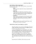
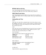
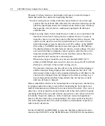
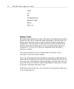
SETUP SYSTEM MENU
CONTRAST 5
BACKLIGHT ON
DIGITAL I/O
IEEE-488 ADDRESS
2
RS-232 BAUD RATE
115200
SET DATE
8/1/06
SET TIME
09:01:36AM
DATE FORMAT
MM/DD/YY
TIME FORMAT
12 HOUR AM/PM
LANGUAGE ENGLISH
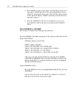
Using the Line Switch and Inrush Capabilities
The following
terms
describe available settings for the Line Switch (Channel
1 only) and commands that can be initiated. All settings and commands can
be made from the front panel interface or by way of a control interface. Most
settings take affect on the next communication with the device-under-test.
Line On
A command initiated by pressing the front panel LINE ON/OFF key when the
LED is extinguished, or by means of a command issued via a control
interface. Note that this is not necessarily the state of the internal line switch.
Line Off
A command initiated by pressing the front panel LINE ON/OFF key when the
LED is illuminated, or by means of a command issued via a control interface.
Note that this is not necessarily the state of the internal line switch.
Rearm
A command initiated by pressing one of the front panel, F1 through F4 keys,
available when the LINE ON/OFF LED is illuminated, or by means of a
command issued via a control interface
Using the Line Switch
Make a signal connection to the device-under-test by pressing the front panel
LINE ON/OFF key with the internal line switch set to ENABLE. Its lighted
LED indicates connection.
CAUTION:
When the line switch is set to DISABLED, it is actually held in
the ON (shorted) state. Do not connect the A+ and LINE terminals to different
Содержание Xitron 2801
Страница 1: ...USER GUIDE 2801 2802 Advanced Single and Dual Channel Power Analyzers...
Страница 2: ...2 2801 2802 Power Analyzer User Guide...
Страница 10: ...10 2801 2802 Power Analyzer User Guide...
Страница 19: ...Functional Description 19 Voltage Input Attenuator Figure 2 Voltage Input Attenuator Block Diagram...
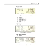
Страница 101: ...Printing Results 101 Figure 66 Configuration Printout...
Страница 102: ...102 2801 2802 Power Analyzer User Guide Figure 67 Waveform Channel 1 Real time...
Страница 103: ...Printing Results 103 Figure 68 Waveform Channe1 Distortion...
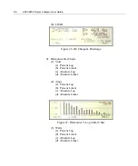
Страница 104: ...104 2801 2802 Power Analyzer User Guide Figure 69 History Chart VOLTS ACDC Trends View...
Страница 105: ...Printing Results 105 Figure 70 History Chart AMPS PERCENT THD Extents View...
Страница 106: ...106 2801 2802 Power Analyzer User Guide Figure 71 Harmonics Listing page 1...
Страница 107: ...Printing Results 107 Figure 72 Harmonics Listing page 2...
Страница 145: ...Sending Commands and Interrogatives 145...
Страница 147: ...Appendix A Physical Specifications 147...
Страница 153: ...Appendix B Measurement Specifications 153...


